JeepParts
My Garage
My Account
Cart
OEM Jeep Compass Crankshaft
Crank Shaft- Select Vehicle by Model
- Select Vehicle by VIN
Select Vehicle by Model
orMake
Model
Year
Select Vehicle by VIN
For the most accurate results, select vehicle by your VIN (Vehicle Identification Number).
5 Crankshafts found


Jeep Compass Crankshaft Part Number: 5047374AC
$605.54 MSRP: $914.00You Save: $308.46 (34%)Ships in 1-2 Business Days
Jeep Compass Crankshaft Part Number: 4884563AD
$681.79 MSRP: $1045.00You Save: $363.21 (35%)Ships in 1-2 Business Days
Jeep Compass Crankshaft Part Number: 68001693AC

Jeep Compass Crankshaft Part Number: 68001694AC

Jeep Compass Crankshaft Part Number: 4884561AD
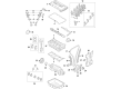
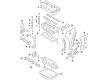
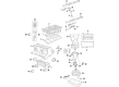
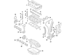
Jeep Compass Crankshaft
Choose OEM Crankshaft that meet Jeep factory standards. Jeep designs and tests every component for precision and durability. Each Crankshaft follows strict manufacturing steps to lock in quality and fit. If your Jeep Compass matters to you, OEM parts make the smart choice. You'll get the exact look, feel, and performance you expect. Shop genuine Compass parts at the highly competitive prices online. Enjoy a manufacturer's warranty, a hassle-free return policy, and rapid delivery. No more guesswork with off brands. Get genuine parts with exact fit and true factory performance. Shop with confidence today at JeepPartsDeal.com.
Jeep Compass Crankshaft Parts and Q&A
- Q: How to Safely Extract the Crankshaft from an Engine Assembly on Jeep Compass?A:Before removing the crankshaft, the engine assembly should be taken from the car and then the transaxle needs to be separated from the engine. You also have to remove the flex plate/flywheel as well as the crankshaft rear oil seal. Next, take off the engine from the lift chain and put it on a repair stand for repair. Afterwards, remove the engine oil and filter. After that, remove the crankshaft vibration damper, the water pump pulley, the engine mount support bracket and the Oil Pan. Also, pull out the timing chain cover and timing chain and then remove the balance shaft module and the crankshaft sprocket. You need to remove the sensor retaining bolt from the crankshaft and lift out the ladder frame to get to the sensor. Whenever the Piston or the connecting rod must be replaced, unbolt the cylinder head first. Use a permanent marker to give each connecting rod and cap a cylinder number; never stamp them with a number stamp or punch to prevent damage. When removing connecting rods, handle the bolts and caps carefully so as not to hurt the fracture rod and cap surfaces and do not recycled the rods' bolts. Afterwards, the main bearing caps get taken out, allowing you to lift the crankshaft clear of the block and make sure it does not scratch the main bearings along the way.
- Q: What Are the Steps Involved in Installing a Crankshaft on Jeep Compass?A:The crankshaft is held up by five main bearings and all the upper bearing shells inside the crankcase have oil grooves and holes, but the lower ones are plain. A two-piece thrust bearing on the number three main bearing journal handles crankshaft end play. Wash the main bearing cap bolt holes with Mopar brake parts cleaner, then vacuum them using compressed air. Make certain that the oil holes and the groove in the bearing shells all line up with the oil holes in the engine block while securing the bearing tabs. After machine work on the crankshaft, you should balance it with the target ring in place. Clean the crankshaft and target ring with the Mopar brake parts cleaner and then blast them dry using compressed air. Every time you mount a crossbow, start by screwing the nuts into the target ring at spot #1, ensure they are properly engaged and tighten them all to 13 Nm (110 in-lbs) using the correct order. After applying trans gel to the thin side, position the thrust bearings so their notches are located near the crankshaft. Slip the thrust bearings into the engine block, careful not to let the oil go on the part that touches the ladder frame since it can harm the RTV seal. Lubricate the crankshaft bearings and journals before you fit the crankshaft into the engine block. Secure the lower main bearings into the main bearing cap, make sure the tabs align correctly and after that bolt the main bearing caps to the engine block, ensuring all of the bolt threads are clean and dry before installing them. Correctly aligning the thrust bearing requires the crankshaft to reach its limits: forward when the number 4 piston is at TDC, then backward and then using a tool placed in between the crankshaft counterweight and the rear cylinder block to wedge it into the forward limit. Look at the bolt heads to choose the proper torque level, since the requirements differ for each kind of main bolt. Once the bolt heads match the standard, tighten them first to 15 Nm (11 ft. lbs.), next to 27 Nm (20 ft. lbs.) and then rotate them an extra 45° past the first tightening step. Should the bolt heads not align, tighten at 15 Nm (11 ft. lbs.), then to 45 Nm (33 ft. lbs.) and turn the extra 45° after that. Take out the wedge tool and measure the turning torque of the crankshaft. Its maximum should be 5.6 Nm (50 in. lbs.) and also check the crankshaft's end play. Connecting Rod Bearings and caps should be installed and you should use new fasteners for them, tightened to a value of 20 Nm + 90° (15 ft. lbs.) + 90°. After that, mount the ladder frame assembly, balance shaft module, crankshaft position sensor and cylinder head (if removed). Assemble the front crankshaft sprocket, install the timing chain, put on the timing chain front cover, set up the Oil Pan, fit the rear crankshaft oil seal, place the front crankshaft oil seal, dowel the engine mount support bracket, fit the crankshaft vibration damper and lastly, add the water pump pulley. After taking the engine off the stand, hook up the engine lift chain and then put in the crankshaft's rear oil seal and drive plate/flex plate using fresh, tightened bolts that are set to 95 Nm (70 ft. lbs.). Secure the transaxle to the engine, tightening the bolts in the bellhousing to 101 Nm (75 ft. lbs.) and assemble the engine. Put a new Oil Filter in place, add oil and coolant, start the engine briefly, check for leaks and mount the engine cover.


Related Jeep Compass Parts
 Jeep Compass Oil Drain Plug
 Jeep Compass Camshaft Seal
 Jeep Compass Cylinder Head
 Jeep Compass Engine Oil Cooler
 Jeep Compass Intake Valve
 Jeep Compass Lash Adjuster
 Jeep Compass Oil Filler Cap
 Jeep Compass Rod Bearing
 Jeep Compass Spool Valve
 Jeep Compass Timing Cover
 Jeep Compass Valve Stem Seal
 Jeep Compass Variable Timing Sprocket