JeepParts
My Garage
My Account
Cart
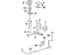
OEM 2007 Chrysler Pacifica Steering Knuckle
Front Steering Knuckle- Select Vehicle by Model
- Select Vehicle by VIN
Select Vehicle by Model
orMake
Model
Year
Select Vehicle by VIN
For the most accurate results, select vehicle by your VIN (Vehicle Identification Number).
2 Steering Knuckles found

2007 Chrysler Pacifica Knuckle, Front Passenger Side Part Number: 4743144AB
$334.34 MSRP: $414.00You Save: $79.66 (20%)Ships in 1-2 Business DaysProduct Specifications- Other Name: Knuckle - Front; Steering Knuckle, Front Right; Knuckle Front
- Position: Front Passenger Side
- Item Weight: 7.00 Pounds
- Item Dimensions: 13.4 x 10.2 x 4.3 inches
- Condition: New
- Fitment Type: Direct Replacement
- SKU: 4743144AB
- Warranty: This genuine part is guaranteed by Mopar's factory warranty.
- Product Specifications
- Other Name: Knuckle - Front; Steering Knuckle, Front Left; Knuckle Front
- Position: Front Driver Side
- Item Weight: 7.10 Pounds
- Item Dimensions: 13.4 x 10.4 x 4.3 inches
- Condition: New
- Fitment Type: Direct Replacement
- SKU: 4743145AB
- Warranty: This genuine part is guaranteed by Mopar's factory warranty.
2007 Chrysler Pacifica Steering Knuckle Parts and Q&A
- Q: How to Install a Steering Knuckle on 2007 Chrysler Pacifica?A: If the hub and bearing must be installed first, center them inside the knuckle and place the wheel speed sensor at the rear end. Replace the threaded holes and use a crisscross pattern to tighten each bolt to around 65 Nm (45 ft. lbs.), but don't tighten all of them at once. Clean the spot where the stud touches the knuckle on the ball joint with a shop cloth and Mopar® Brake Parts Cleaner before installing the knuckle. Attach the knuckle to the ball joint stud and fasten a NEW steering knuckle to the steering knuckle nut by turning it to 81 Nm (60 ft. lbs.) plus another 90° with a crowfoot wrench on a torque wrench. Align the halfshaft stub shaft with the hub and bearing, as you do not want to allow the clevis-to-knuckle bolts to turn during installation; secure them by holding the bolts as you put in the nuts. With the left knuckle, place the lower strut assembly in contact with the upper knuckle. Add the two strut clevis-to-knuckle bolts, tighten their nuts to 88 Nm and then add a further 90° of torque. When it's time for the right knuckle, follow the steps you used for the left. Just like before, clean where the tie rod stud will join and only then should you install it in the knuckle steering arm. Slide the tie rod stud into the knuckle steering arm, screw on the nut tight to the maximum torque of 47 Nm (35 ft. lbs.) and turn the nut an additional 180° after tightening. Install the wheel speed sensor cable grommet in the clip fitting at the knuckle and close the clip. Place the routing bracket for the wheel speed sensor onto the strut assembly and tighten the screw to 13 Nm (115 in. lbs.). Secure the wheel speed sensor connector and routing clip to the outer end of the frame rail reinforcement and finally link the vehicle wiring harness to the connector. Position the rotor first, then install the caliper and adapter together, taking care the speed sensor is correctly placed. Put the washer and hub nut on the stub shaft at the end of the halfshaft and apply brakes using a helper's help as you tighten the nut to 244 Nm (180 ft. lbs.). On the hub nut and stub shaft, put the spring washer and hub nut lock, securing it with a NEW cotter pin. Assemble the tire and wheel, tighten the wheel mounting nuts to the recommended pressure, lift the vehicle, pump the brakes many times, check brake fluid as needed and have the wheels aligned.
Related 2007 Chrysler Pacifica Parts
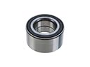 2007 Chrysler Pacifica Wheel Bearing
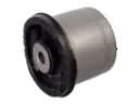 2007 Chrysler Pacifica Axle Beam Mount
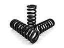 2007 Chrysler Pacifica Coil Springs
 2007 Chrysler Pacifica Control Arm
 2007 Chrysler Pacifica Control Arm Bolt
 2007 Chrysler Pacifica Control Arm Bushing
 2007 Chrysler Pacifica Crossmember Bushing
 2007 Chrysler Pacifica Lateral Link
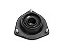 2007 Chrysler Pacifica Shock And Strut Mount
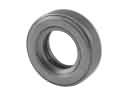 2007 Chrysler Pacifica Strut Bearing
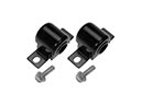 2007 Chrysler Pacifica Sway Bar Bushing
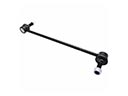 2007 Chrysler Pacifica Sway Bar Link