JeepParts
My Garage
My Account
Cart
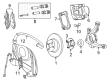
OEM 2007 Chrysler PT Cruiser Steering Knuckle
Front Steering Knuckle- Select Vehicle by Model
- Select Vehicle by VIN
Select Vehicle by Model
orMake
Model
Year
Select Vehicle by VIN
For the most accurate results, select vehicle by your VIN (Vehicle Identification Number).
6 Steering Knuckles found


2007 Chrysler PT Cruiser Knuckle, Front Driver Side Part Number: 5272487AC
$242.25 MSRP: $318.00You Save: $75.75 (24%)Ships in 1-2 Business DaysProduct Specifications- Other Name: Knuckle - Front; Steering Knuckle, Front Left
- Position: Front Driver Side
- Replaces: 5272487AB
- Item Weight: 12.00 Pounds
- Item Dimensions: 10.3 x 10.5 x 5.9 inches
- Condition: New
- Fitment Type: Direct Replacement
- SKU: 5272487AC
- Warranty: This genuine part is guaranteed by Mopar's factory warranty.


2007 Chrysler PT Cruiser Knuckle, Front Passenger Side Part Number: 5272486AC
$213.00 MSRP: $316.00You Save: $103.00 (33%)Ships in 1-3 Business DaysProduct Specifications- Other Name: Knuckle - Front; Steering Knuckle, Front Right
- Position: Front Passenger Side
- Replaces: 5272486AB
- Item Weight: 10.90 Pounds
- Item Dimensions: 10.5 x 10.4 x 6.0 inches
- Condition: New
- Fitment Type: Direct Replacement
- SKU: 5272486AC
- Warranty: This genuine part is guaranteed by Mopar's factory warranty.

2007 Chrysler PT Cruiser Knuckle, Front Passenger Side Part Number: 5272478AE
$239.17 MSRP: $338.00You Save: $98.83 (30%)Ships in 1-2 Business DaysProduct Specifications- Other Name: Knuckle - Front; Steering Knuckle, Front Right
- Position: Front Passenger Side
- Replaces: 5272478AB
- Item Weight: 10.00 Pounds
- Item Dimensions: 10.4 x 10.4 x 10.5 inches
- Condition: New
- Fitment Type: Direct Replacement
- SKU: 5272478AE
- Warranty: This genuine part is guaranteed by Mopar's factory warranty.

2007 Chrysler PT Cruiser Knuckle, Front Passenger Side Part Number: 5272492AB
$215.45Ships in 1-2 Business DaysProduct Specifications- Other Name: Knuckle - Front; Steering Knuckle, Front Right; Knuckle Front
- Position: Front Passenger Side
- Item Weight: 10.40 Pounds
- Item Dimensions: 11.5 x 8.4 x 4.7 inches
- Condition: New
- Fitment Type: Direct Replacement
- SKU: 5272492AB
- Warranty: This genuine part is guaranteed by Mopar's factory warranty.
2007 Chrysler PT Cruiser Knuckle, Front Driver Side Part Number: 5272479AE
$273.32 MSRP: $338.00You Save: $64.68 (20%)Ships in 1-2 Business DaysProduct Specifications- Other Name: Knuckle - Front; Steering Knuckle, Front Left
- Position: Front Driver Side
- Replaces: 5272479AB
- Item Weight: 9.70 Pounds
- Condition: New
- Fitment Type: Direct Replacement
- SKU: 5272479AE
- Warranty: This genuine part is guaranteed by Mopar's factory warranty.
- Product Specifications
- Other Name: Knuckle - Front; Steering Knuckle, Front Left; Knuckle Front
- Position: Front Driver Side
- Item Weight: 11.00 Pounds
- Item Dimensions: 12.7 x 12.5 x 6.3 inches
- Condition: New
- Fitment Type: Direct Replacement
- SKU: 5272493AB
- Warranty: This genuine part is guaranteed by Mopar's factory warranty.
2007 Chrysler PT Cruiser Steering Knuckle Parts and Q&A
- Q: How to Install a Steering Knuckle on 2007 Chrysler PT Cruiser?A: Before fitting the steering knuckle, clear the matching area between the halfshaft C/V joint and the knuckle, apply Mopar(R) Wheel Bearing Grease or Mopar(R) Multi-Purpose Grease around the circumference on both mating surfaces and be sure no grease touches the ABS tone wheel. Degrease and wipe both areas where the hub and bearing sit against the C/V joint in the knuckle. Guide the hub of the knuckle over the splines found on the outer joint of the halfshaft C/V. Bolt the knuckle onto the ball joint stud by putting the bolt hole in the knuckle boss into the notch along the stud. Replace the damaged ball joint stud pinch bolt and put a new nut on it. Then tighten the nut to 95 Nm (70 ft. lbs.). The knuckle-mounted bolts are serrated; therefore, they must not turn until after the installing nuts are secured. Make sure the bottom end of the strut assembly is over the mounting point on the knuckle, line up the holes and use the two bolts installed from the car's front. Put the nuts on and torque them to 163 Nm (120 ft. lbs.) as you hold the bolts. Put the heat shield on the knuckle arm so that it faces straight from the steering gear and round it out so the hole in the shield lines up with the tie rod end mounting hole. Put the tie rod ball stud into the hole in the knuckle arm, screw the mounting nut on, hold the tie rod end stud with a wrench and tighten the nut to a specific torque of 54 Nm (40 ft. lbs.). Attach the wheel speed sensor with heat shield to the knuckle and tighten the screw as much as 12 Nm (105 in. lbs.). Place the brake rotor, disc brake caliper and adapter onto the vehicle. Remove any obstructions from the halfshaft outer C/V joint threads and after that put on the washer and tighten the hub nut onto the end of the halfshaft. Grasping the spindle, a helper holds the wheel brakes tight while you tighten the hub nut until it reaches 244 Nm (180 ft. lbs.). Slide the spring washer and lock nut over the hub nut, pass the cotter pin through the notches on the lock nut and the halfshaft hole and press the cotter pin's ends tightly over the lock nut. Next, put on the tire and wheel assembly, fastening the wheel mounting nuts to 135 Nm (100 ft. lbs.), put the vehicle on the ground and wheel align as required.
Related 2007 Chrysler PT Cruiser Parts
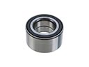 2007 Chrysler PT Cruiser Wheel Bearing
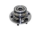 2007 Chrysler PT Cruiser Wheel Hub
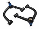 2007 Chrysler PT Cruiser Control Arm
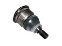 2007 Chrysler PT Cruiser Ball Joint
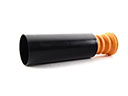 2007 Chrysler PT Cruiser Bump Stop
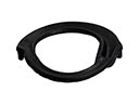 2007 Chrysler PT Cruiser Coil Spring Insulator
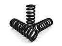 2007 Chrysler PT Cruiser Coil Springs
 2007 Chrysler PT Cruiser Shock And Strut Mount
 2007 Chrysler PT Cruiser Sway Bar Bracket
 2007 Chrysler PT Cruiser Sway Bar Bushing
 2007 Chrysler PT Cruiser Sway Bar Kit
 2007 Chrysler PT Cruiser Sway Bar Link