JeepParts
My Garage
My Account
Cart
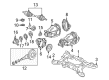
OEM Chrysler 300 Crossmember Bushing
Crossmember Mount- Select Vehicle by Model
- Select Vehicle by VIN
Select Vehicle by Model
orMake
Model
Year
Select Vehicle by VIN
For the most accurate results, select vehicle by your VIN (Vehicle Identification Number).
3 Crossmember Bushings found


Chrysler 300 Crossmember Bushing, Front Driver Side Part Number: 4895391AD
$92.37 MSRP: $138.00You Save: $45.63 (34%)Ships in 1-3 Business Days
Chrysler 300 Crossmember Bushing, Front Passenger Side Part Number: 4895390AD
$92.37 MSRP: $138.00You Save: $45.63 (34%)Ships in 1-3 Business Days


Chrysler 300 Crossmember Bushing, Rear Part Number: 4782861AA
$9.11 MSRP: $13.10You Save: $3.99 (31%)Ships in 1-2 Business Days
Chrysler 300 Crossmember Bushing
Choose OEM Crossmember Bushing that meet Chrysler factory standards. Chrysler designs and tests every component for precision and durability. Each Crossmember Bushing follows strict manufacturing steps to lock in quality and fit. If your Chrysler 300 matters to you, OEM parts make the smart choice. You'll get the exact look, feel, and performance you expect. Shop genuine 300 parts at the highly competitive prices online. Enjoy a manufacturer's warranty, a hassle-free return policy, and rapid delivery. No more guesswork with off brands. Get genuine parts with exact fit and true factory performance. Shop with confidence today at JeepPartsDeal.com.
Chrysler 300 Crossmember Bushing Parts and Q&A
- Q: How Does Crossmember Bushing Installation Affect Ride Quality and Longevity on Chrysler 300?A:Be certain you are installing the bushing on the correct side; the travel limiter of the left-side bushing is tipped right, but on the right side it is tipped left. Putting in the bushing in its former position ensures the vehicle handles and lasts properly, following the previous reference marks. Set the bushings in the crossmember opening so that their can flange matches with the reference marks. Utilize Receiver 9031-6, Press C-4212F and Installer 9031-7A and set up the Installer to clear the compression link bracket as you install. Screw the Press screw-driver into the bushing to push it into the crossmember until the board touches the surface. After setting aside the tools, make sure the bushing lines up with the marks and fasten the compression link to the crossmember with the bolt and nut, but don't tighten yet. Hang the crossmember up to the body mounts and place the propeller shaft over the rear differential. Line up the Shock Absorbers with the pockets in the spring links. Set up the left side crossmember mounting bolts so they don't tighten yet, then lower the jack enough that the right side of the crossmember is just above the isolators, so they can be properly installed. Place the coil spring into the spring pocket along with the isolators, push the lower end of the shock into place and set in the lower shock bolt and nut but do not tighten yet. For vehicles with AWD, place your spacers on the right crossmember mount bushings before raising the crossmember and tighten the right bolts. Lift the jack to remove strain on the crossmember, then take out the left side mounting bolts and move the crossmember away to install the coils with isolators present. Set up the Coil Springs on the left side as well, ensuring the left side crossmember mounting bolts are tight. Move the crossmember until the mounts are above the on-car marks, checking that the distance between the shock link and the weld flange is at least 12 mm. Then tighten each of the four crossmember bolts to 180 Nm (133 ft. lbs.) and remove the jack and bungee cord. Set the propeller shaft arrow marks together and add the rear flange bolts, tighten them to 81 Nm (60 ft. lbs.). Attach the fuel filler tube, clip the left rear wheel speed sensor cable onto the routing clip and link the left rear wheel speed sensor to the connector on the right. Pull the fuse sensors up and plug the connectors into the body wiring harness connector, with the clips locked in place. If your vehicle uses standard or premium disc brakes, insert the caliper guide pins into the caliper adapter, put the caliper through the rear suspension and onto the brake pads and tighten the caliper guide pins by hand to 31 Nm (23 ft. lbs.). To install SRT8 disc brakes, first hold the spring link and put the caliper on top of the rotor, installing the pads with the bolts torqued to 130 Nm (96 ft. lbs.). Route the rear Parking Brake Cable above the crossmember in the back and join the front parking brake cable to the right rear parking brake cable. After installing the bracket for the front parking cable and the rear exhaust system, set the tires and wheels into place, secure them with 150 Nm (110 ft. lbs.) on the nuts. Move the vehicle down so that the rear wheels are a little off the floor and engage and disengage the parking brake, while checking if the wheels don't turn. Reduce the vehicle all the way, link the negative cable to the battery, press the brake pedal several times to verify proper operation and set the vehicle up on an alignment rack. Tighten both mounting bolt nuts on the shock absorber to 72 Nm (53 ft. lbs.) and tighten the compression link bolt and nut to the crossmember to 85 Nm (63 ft. lbs.), then do a wheel alignment, ensuring you do not interfere with the tension link clearance.
- Q: How to Service and Repair a Rear Crossmember Bushing for Front Mount on Chrysler 300?A:The first step to service and repair the Rear Crossmember bushing is removing the battery negative cable and raising the car or truck. On both sides of the rear, remove the wheel mounting nuts and the tire plus wheel assembly. The following step is to take off the rear exhaust system and put alignment index marks on the coupler and axle flange. Remove all flange bolts that secure the shaft coupler to the axle, then tie the propeller shaft with a bungee cord. Pull the front Parking Brake Cable from its position on the equalizer and remove it from the vehicle, then detach the rear crossmember routing bracket from its front flange. With vehicles having disc brakes, start by losing the bolts that hold the guide pin inside the caliper, dropping off the caliper from the brake adapter and placing it above the rear suspension. To service your SRT8 disc brakes, use a trim stick; push the pistons back in, hold the spring link and then take out the mounting bolts. Take out the wheel speed sensor connectors and unlock the left wheel speed sensor cable. Unbolt the lower mounting bolts of the shock absorbers and put marks on the rear crossmember location on the body. Put the jack stands under the front end of the engine cradle and then put a jack beneath the rear axle differential. Take the fuel filler tube off and detach the two bolts that keep the crossmember in place at the front and rear sections. Ask a helper to slowly let down the crossmember, so you can take out the propeller shaft and use jack stands to support the rear suspension assembly. Take the Coil Springs with isolators off the spring links and make a mark on the crossmember where the bushings were located. Take out the nut and bolt joining the compression link to the crossmember, followed by taking out the travel limiter by grinding the bushing inner metal sleeve. Slide Support 9031-9 into the crossmember around the bushing bore, tighten both set-screws and place Brace 9031-10 in between the support and the flange of the bore. Make sure the set-screws are touching the brace, but don't tighten them too tightly. Lubricate Press C-4212F's screw threads, then gather the tools up over the bushing. Apply more pressure to the screw-drive, remove the bushings from the crossmember and remove all your tools. Check that the new bushing is the right one for the side and place it with the reference markings you made while removing the old one face up. Set the bushing in place on the crossmember and then fit the tools over the bushing, so the installer can move the compression link bracket away. Install the bushing by tightening the press screw-drive until the bushing flange touches the crossmember's surface, then take out the tools to confirm alignment with the reference marks. Insert the bolt through the hole in the crossmember and connect and position the compression link and nut without tightening. Pull the crossmember up to its position at the body mounting points, add the propeller shaft to the rear axle differential flange and line up the shock absorbers in the pockets of the spring links. Put in the left side crossmember bolts for now and allow the left coil spring to hang, then lift the vehicle slightly so you can fit the right side coil spring. Slide the coil spring with isolators into the spring pocket and guide it into place, then put in the lower mounting bolt but don't tighten it. When you're working on AWD vehicles, apply spacers on the top of the right crossmember mount bushings before elevating the crossmember. Install the crossover on the right first, then insert and loosely access the right side bolts. Follow the steps for the right side on the left side, paying attention that the crossmember mounts fit over the location marks. Check and change the distance between the tension link and the weld flange on each side so that there is at least 12 mm of space available between them. All four bolts for the crossmembers should be tightened to 180 N.m (133 ft.lbs.), the jack is then removed from the rear axle differential and you remove the bungee cord used to support the propeller shaft. Place the shaft index marks together and put in the bolts that hold the rear coupler to the axle flange, tightening them to 81 N.m (60 ft.lbs.). Put the fuel filler tube back, attach the rear wheel speed sensor cable to the left and connect the speed sensor connectors to the body wiring harness. If you have standard or premium disc brakes, place the caliper on top of the brake pads and the caliper adapter, making sure to do this without crossing the guide pin bolts and secure them with the wrench to 31 N.m (23 ft.lbs.). Guide the spring link and push the caliper with pads onto the brake disc for the SRT8 model, then set all four caliper bolts and tighten them to 130 N.m (96 ft.lbs.). Feed the parking brake cable, install the front parking brake cable and fit the routing bracket screw. Refit the rear exhaust system, the tires and wheels and twist the wheel mounting nuts until they reach 150 N.m (110 ft.lbs.). Pull down the vehicle and then press the parking brake lever until it comes to a stop; watching to make sure the rear wheels don't turn. Afterward, attach the battery's negative cable, press the brake pedal to confirm it feels strong, mount the vehicle on an alignment rack and secure the nuts of both the shock absorber lower mounts and compression link bolts at the crossmember to the stated torque.


Related Chrysler 300 Parts
 Chrysler 300 Wheel Bearing
 Chrysler 300 Lug Nuts
 Chrysler 300 Steering Knuckle
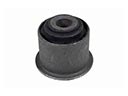 Chrysler 300 Axle Pivot Bushing
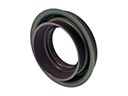 Chrysler 300 Axle Shaft Seal
 Chrysler 300 Coil Spring Insulator
 Chrysler 300 Control Arm Bolt
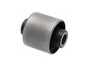 Chrysler 300 Differential Mount
 Chrysler 300 Strut Mounts
 Chrysler 300 Suspension Strut Rod
 Chrysler 300 Sway Bar Bushing
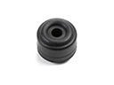 Chrysler 300 Sway Bar Link Bushing