JeepParts
My Garage
My Account
Cart
OEM Dodge Stratus Piston
Engine Pistons- Select Vehicle by Model
- Select Vehicle by VIN
Select Vehicle by Model
orMake
Model
Year
Select Vehicle by VIN
For the most accurate results, select vehicle by your VIN (Vehicle Identification Number).
11 Pistons found


Dodge Stratus Vibration Damper Part Number: 5142303AB
$56.55 MSRP: $81.25You Save: $24.70 (31%)Ships in 1-3 Business Days
Dodge Stratus Piston Part Number: 5018627AD
$316.65 MSRP: $576.00You Save: $259.35 (46%)Ships in 1-2 Business Days
Dodge Stratus Piston Part Number: MD357067
$89.79 MSRP: $133.00You Save: $43.21 (33%)Ships in 1-2 Business DaysDodge Stratus Piston Part Number: MD357068
$45.47 MSRP: $65.35You Save: $19.88 (31%)Ships in 1-2 Business Days
Dodge Stratus Piston Part Number: MD309399
$8.15 MSRP: $10.34You Save: $2.19 (22%)Ships in 1-2 Business Days
Dodge Stratus Piston Part Number: MD367089
Dodge Stratus Piston Part Number: MD309393

Dodge Stratus Piston Part Number: 4796212
Dodge Stratus Piston Part Number: MD357066

Dodge Stratus Piston Part Number: 5103509AA

Dodge Stratus Piston Part Number: 68067617AA
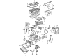
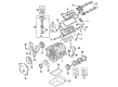
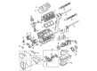
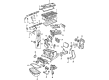
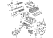
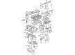
Dodge Stratus Piston
Choose OEM Piston that meet Dodge factory standards. Dodge designs and tests every component for precision and durability. Each Piston follows strict manufacturing steps to lock in quality and fit. If your Dodge Stratus matters to you, OEM parts make the smart choice. You'll get the exact look, feel, and performance you expect. Shop genuine Stratus parts at the highly competitive prices online. Enjoy a manufacturer's warranty, a hassle-free return policy, and rapid delivery. No more guesswork with off brands. Get genuine parts with exact fit and true factory performance. Shop with confidence today at JeepPartsDeal.com.
The Piston is a very important tool, which greatly increases the prospects of Dodge Stratus automobiles that were manufactured between 1995 and 2005. Constructed with lightweight aluminum alloys, these pistons will deliver optimum conversion of energy from combustion to kinetic energy of a vehicle. Some of the types of Piston include trunk pistons for both petrol and diesel motors as well as racing pistons ideal for high RPMs due to racing car activities. This adaptability makes the Piston to fit various models of Stratus that have different engine sizes from 2.0 L to 3.0 L including coupe and sedan models The above exhaustion denotes that the performance of the Dodge Stratus is boosted by efficiency of the pistons through an averagely higher fuel consumption of between 20-21 city mg and 26-29 highway mpg. Also, the Piston has a great responsibility of maintaining safety and longevity of the engines something that makes the Stratus to gain a reputation of a reliable mid-size car. The innovations of design in the features of the Piston and engineering qualities make the Dodge Stratus models distinguish themselves in the automotive industry, and it becomes quite attractive for buyers, who are focused on the balance between the price and performance.
Dodge Stratus Piston Parts and Q&A
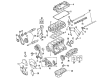
- Q: How to Replace a Piston and Its Connecting Rod on Dodge Stratus?A:Before removing and swapping the piston and connecting rod, you should first take off the cylinder head, Oil Pan and Balance Shaft Carrier Assembly. After applying a ridge reamer on the top ridge of your cylinder bores, take out your pistons, making sure the piston crown is still clean. You'll notice that the pistons have been stamped this way in the front half facing the engine. Wedge off the pistons and connecting rods on the top of the cylinder block by turning the Crankshaft until all the connecting rods are centered in the cylinders. Use a permanent ink or paint marker to label each rod cap with the main bearing number, instead of a number stamp or punch to be safe. Without hurting the surface, take out the connecting rod bolts and cap and never reuse the bolts again. When protecting the crankshaft journal and fractured rod, install Special Tool 8189 and connecting rod guides, then gently push each piston and rod assembly from inside the cylinder. After the guides are off, fit the bearing cap back over the mating rod. Do this for all the piston and connecting rod pairs and afterwards take out the piston rings. During installation, the gaps between each piston ring should vary, not match the oil ring's gap width. Your first step should be to assure the ends of the oil ring expander are connected and rail spacing is accurate before doing anything else. After oiling the piston head and rings, slide the compressor over them, being careful the ring positions are not altered. Make sure the piston's directional stamp is within view of the front of the engine. Move the crankshaft until the connecting rod lies in the middle of the cylinder bore and spray a bit of clean engine oil on it. After placing the upper half of the bearing in the connecting rod, apply Special Tool 8189, the connecting rod guides and carefully tap the piston into the bore as you guide the rod home. Once you have removed the guides, lubricate the bolt's threads with a little engine oil before putting new bolts in place. Place the lower bearing half into the connecting rod cap and secure the cap in place with all fasteners only finger tight. Then, after joining the cap and bottom half, alternately torque the bolts to their proper values. Tighten all the bolts to 27 Nm on your tool and tighten the additional 1/4 TURN by hand. Measure the space between the engine and rod end with a feeler gauge, then assemble the Balance Shaft Carrier Assembly, oil pan and cylinder head.
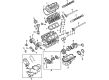
- Q: How to Remove and Install Piston and Connecting Rod Assemblies in an Engine on Dodge Stratus?A:To remove the pistons, use a good ridge reamer to eliminate the top of the bores, with the piston tops still covered. It is necessary to pull out the pistons and connecting rods from the top of the cylinder block after rotating the Crankshaft to center each connecting rod within the bore. Set a mark on both the connecting rod and bearing caps using a permanent ink marker or scribe, without damaging the fracture areas on the joint surfaces. Eliminate the connecting rod cap and pop in Special Tool 8189 Connecting Rod Guides into the connecting rod you're pulling, then remove one piston and connecting rod assembly at a time from the bore, not scratching the crankshaft journals. Don't forget to replace the bearing cap after removal to keep the mating rod protected. During installation, fit the piston rings first, making sure that the spaces between your compression rings are staggered and that your oil ring expanders sit directly against the rail gaps. Place the piston head and rings into clean engine oil, slide the ring compressor over the piston, tighten with the special wrench and guarantee the ring positions do not change. Put both these holes together and line them up, then, coat the bearing surface in clean engine oil and install Special Tools 8189 Connecting Rod Guides. Both pistons should have an arrow and "F" (Front) inscribed above the pin boss and these should point toward the front of the engine, with the connecting rod oil hole on the major thrust side of the block. Centere the connecting rod journal in the cylinder bore, fit in the rod and piston and slide the rod over the journal of the crankshaft. Drop the piston into the cylinder bore with a hammer handle and move the connecting rod into place on its journal as you do so. With engine oil, coat the rod bolts and bearing surface, mount the connecting rod cap and bearing and tighten until you reach 27 Nm (20 ft. lbs.) followed by a 1/4 turn.


Related Dodge Stratus Parts
 Dodge Stratus Engine Mount
 Dodge Stratus Oil Pump
 Dodge Stratus Balance Shaft Chain
 Dodge Stratus Camshaft
 Dodge Stratus Crankshaft Gear
 Dodge Stratus Crankshaft Thrust Washer
 Dodge Stratus Cylinder Head
 Dodge Stratus Intake Valve
 Dodge Stratus Motor And Transmission Mount
 Dodge Stratus Rod Bearing
 Dodge Stratus Timing Belt Tensioner
 Dodge Stratus Timing Chain Tensioner