JeepParts
My Garage
My Account
Cart
OEM Jeep Commander Front Cross-Member
Front Engine Cross Member- Select Vehicle by Model
- Select Vehicle by VIN
Select Vehicle by Model
orMake
Model
Year
Select Vehicle by VIN
For the most accurate results, select vehicle by your VIN (Vehicle Identification Number).
1 Front Cross-Member found


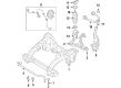
Jeep Commander Engine Cradle, Front Part Number: 52089493AI
Jeep Commander Front Cross-Member
Choose OEM Front Cross-Member that meet Jeep factory standards. Jeep designs and tests every component for precision and durability. Each Front Cross-Member follows strict manufacturing steps to lock in quality and fit. If your Jeep Commander matters to you, OEM parts make the smart choice. You'll get the exact look, feel, and performance you expect. Shop genuine Commander parts at the highly competitive prices online. Enjoy a manufacturer's warranty, a hassle-free return policy, and rapid delivery. No more guesswork with off brands. Get genuine parts with exact fit and true factory performance. Shop with confidence today at JeepPartsDeal.com.
Jeep Commander Front Cross-Member Parts and Q&A
- Q: How to Service and Repair a Front Cross-Member on Jeep Commander?A:For work on the front cross-member, first use engine support fixture No. 8534 or another comparable tool to avoid the engine dropping. Make sure you don't twist the boots while taking out or putting on the front skid plates and rotors. After that, take off the outer tie rod end nut from the ball stud and use puller tool No. 8677 to separate the outer tie rod end from the knuckle. Loose the nut above the Ball Joint, then separate the upper ball joint from the knuckle by using puller tool No. 8677. Take off the axle nuts and insert them back one or two turns. Remove the Speed Sensors and pull out the harness from the support clips. Wheel the lower ball joint nut off and pull the lower ball joint from the knuckle with puller tool No. C-4150A. Take out the axle nuts and unfasten the knuckles and finally remove the lower clevis bolts. For this, connect the sway bar to the engine cradle and then place on the lower Control Arms as you see fit. Take the engine cradle up to its proper place and fit the engine mount bolts into each slot in the cradle; then, add the four cradle bolts. Place the engine cradle as it was during disassembly and screw the front bolts to 203 N.m (150 ft.lbs) and the rear bolts to 122 N.m (90 ft.lbs). Set up the steering device as needed, drop the engine into its mounts and tighten the bolts to 111 N.m or 82 ft.lbs.

Related Jeep Commander Parts
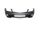 Jeep Commander Bumper
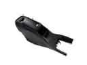 Jeep Commander Center Console
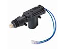 Jeep Commander Door Lock Actuator
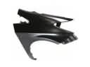 Jeep Commander Fender
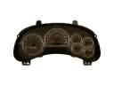 Jeep Commander Instrument Cluster
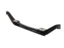 Jeep Commander Axle Beam
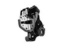 Jeep Commander Door Lock
 Jeep Commander Exhaust Nut
 Jeep Commander Grille
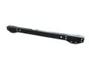 Jeep Commander Rear Crossmember
 Jeep Commander Tailgate Lock
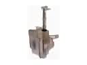 Jeep Commander Windshield Washer Fluid Reservoir