JeepParts
My Garage
My Account
Cart
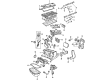
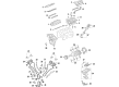
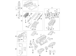
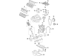
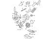
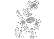
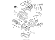
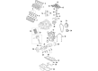
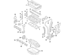
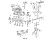
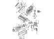
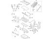
OEM Jeep Rod Bearing
Engine Connecting Rod Bearing- Select Vehicle by Model
- Select Vehicle by VIN
Select Vehicle by Model
orMake
Model
Year
Select Vehicle by VIN
For the most accurate results, select vehicle by your VIN (Vehicle Identification Number).
35 Rod Bearings found


Jeep Bearings Part Number: 5174612AA
$14.57 MSRP: $24.10You Save: $9.53 (40%)Product Specifications- Other Name: Bearing - Connecting Rod; Bearing Kit Connecting Rod Standard See Note; Bearing Kit Connecting Rod Standard
- Replaces: 5093448AB, 5012588AA


Jeep Connecting Rod Bearing Part Number: 5184111AF
$3.76 MSRP: $5.65You Save: $1.89 (34%)Ships in 1-2 Business DaysProduct Specifications- Other Name: Bearing - Connecting Rod; Rod Bearing; Bearing; Bearings; Bearing Connecting Rod +.003Mm See Note; Bearing Connecting Rod +.003Mm
- Replaces: 5184111AE


Jeep Connecting Rod Bearing Part Number: 5184113AF
$3.83 MSRP: $5.65You Save: $1.82 (33%)Ships in 1-2 Business DaysProduct Specifications- Other Name: Bearing - Connecting Rod; Rod Bearing; Bearing; Bearings; Bearing Connecting Rod - .003Mm See Note; Bearing Connecting Rod - .003Mm
- Replaces: 5184113AE


Jeep Connecting Rod Bearing Part Number: 4893952AA
$10.37 MSRP: $15.40You Save: $5.03 (33%)Ships in 1-3 Business DaysProduct Specifications- Other Name: Bearing - Connecting Rod; Rod Bearing; Bearings; Bearing Connecting Rod Standard
- Replaces: 4893836AA, 68088069AA


Jeep Bearing Part Number: 4892950AB
$14.31 MSRP: $21.15You Save: $6.84 (33%)Ships in 1-2 Business DaysProduct Specifications- Other Name: Bearing - Connecting Rod; Bearing Connecting Rod


Jeep Connecting Rod Bearing Part Number: 68362046AA
$16.59 MSRP: $24.55You Save: $7.96 (33%)Ships in 1-2 Business DaysProduct Specifications- Other Name: Bearing Package - Connecting Rod; Rod Bearing; Bearing; Bearings; Bearing Kit Connecting Rod Standard Upper And Lower; Bearing Kit Connecting Rod Standard
- Replaces: 5086003AD, 5086003AC, 5086003AE


Jeep Bearings Part Number: 5012363AE
$16.87 MSRP: $25.00You Save: $8.13 (33%)Ships in 1-2 Business DaysProduct Specifications- Other Name: Bearing - Connecting Rod; Rod Bearing; Bearing Kit Connecting Rod Standard See Note; Bearing Kit Connecting Rod Standard
- Replaces: 5012363AC, 5012363AD, 5018584AB, 5012363AB


Jeep Bearings Part Number: 68052222AB
$18.13 MSRP: $26.80You Save: $8.67 (33%)Ships in 1-2 Business DaysProduct Specifications- Other Name: Bearing - Connecting Rod; Engine Connecting Rod Bearing Set; Connecting Rod Bearing Set; Rod Bearing; Bearing Kit Connecting Rod Standard See Note
- Replaces: 5019447AA, 68052222AA


Jeep Bearings Part Number: 5161294AA
$18.30 MSRP: $27.05You Save: $8.75 (33%)Ships in 1-2 Business DaysProduct Specifications- Other Name: Bearing Kit - Connecting Rod; Bearing Package Connecting Rod Standard: One [1] Upper & One [1] Lower Bearing.
- Replaces: 5012056AA


Jeep Connecting Rod Bearing Part Number: 68029429AC
$16.02 MSRP: $23.55You Save: $7.53 (32%)Ships in 1-2 Business DaysProduct Specifications- Other Name: Bearing - Connecting Rod; Rod Bearing; Bearing; Bearings; Bearing Kit Connecting Rod Standard
- Replaces: 68029429AB, 68029429AA, 68029429AI, 68060359AA


Jeep Bearings Part Number: 4884912AB
$18.19 MSRP: $23.55You Save: $5.36 (23%)Product Specifications- Other Name: Bearing - Connecting Rod; Rod Bearing; Bearing Connecting Rod Standard See Note
- Replaces: 1115A150, 4884912AA


Jeep Rod Bearings Part Number: 2421305
$21.97 MSRP: $27.86You Save: $5.89 (22%)Ships in 1-2 Business DaysProduct Specifications- Other Name: Bearing Package - Connecting Rod; Engine Connecting Rod Bearing; Connecting Rod Bearing Pair; Rod Bearing; Bearings; Connecting Rod Bearing Package, Standard; Includes various connecting rod bearings.


Jeep Connecting Rod Bearing Part Number: 68207790AA
$6.32 MSRP: $7.70You Save: $1.38 (18%)Product Specifications- Other Name: Bearing Package - Connecting Rod; Rod Bearing; Bearing; Bearings; Bearing Kit Connecting Rod Standard
- Replaces: 5086003AB

Jeep Connecting Rod Bearing Part Number: 5047638AC
$3.99 MSRP: $6.00You Save: $2.01 (34%)Ships in 1-2 Business DaysProduct Specifications- Other Name: Bearing - Connecting Rod; Rod Bearing; Bearing; Bearings; Bearing Connecting Rod +3 Micron Used For Upper And Lower; Bearing Connecting Rod +3 Micron See Note
- Replaces: 5047638AB


Jeep Connecting Rod Bearing Part Number: 4893953AA
$9.41 MSRP: $13.95You Save: $4.54 (33%)Ships in 1-2 Business DaysProduct Specifications- Other Name: Bearing - Connecting Rod; Rod Bearing; Bearings; Bearing Connecting Rod - .003Mm; Bearing Connecting Rod - .006Mm
- Replaces: 4893837AA, 68088070AA


Jeep Connecting Rod Bearing Part Number: 4893951AA
$14.57 MSRP: $15.05You Save: $0.48 (4%)Ships in 1-2 Business DaysProduct Specifications- Other Name: Bearing - Connecting Rod; Rod Bearing; Bearings; Bearing Connecting Rod +.003Mm
- Replaces: 4893835AA, 68088068AA


Jeep Connecting Rod Bearing Part Number: 5047637AC
$4.58 MSRP: $6.80You Save: $2.22 (33%)Product Specifications- Other Name: Bearing - Connecting Rod; Rod Bearing; Bearing; Bearings; Bearing Connecting Rod Standard Used For Upper And Lower; Bearing Connecting Rod Standard See Note
- Replaces: 5047637AB


Jeep Connecting Rod Bearing Part Number: 5184112AF
$16.30 MSRP: $23.55You Save: $7.25 (31%)Product Specifications- Other Name: Bearing - Connecting Rod; Engine Connecting Rod Bearing; Connecting Rod Bearing Pair; Rod Bearing; Bearing; Bearings; Bearing Connecting Rod Standard See Note; Bearing Connecting Rod Standard
- Replaces: 5184112AE


Jeep Bearing, Yellow Part Number: 68229247AA
$27.84 MSRP: $40.05You Save: $12.21 (31%)Product Specifications- Other Name: Bearing - Connecting Rod; Rod Bearing; Bearing Kit Connecting Rod Includes Upper And Lower Bearings.
- Replaces: 68147236AA

Jeep Bearing, Blue Part Number: 68229246AA
$29.52 MSRP: $42.60You Save: $13.08 (31%)Product Specifications- Other Name: Bearing - Connecting Rod; Rod Bearing; Bearing Kit Connecting Rod Includes Upper And Lower Bearings.
- Replaces: 68147235AA
| Page 1 of 2 |Next >
1-20 of 35 Results
Jeep Rod Bearing
OEM parts sourced directly from Jeep deliver superior quality, long lasting strength, and a precise fit you can trust. Each item goes through strict quality checks to ensure safety, toughness, and performance that matches your factory equipment. At JeepPartsDeal online shop, you'll get top-quality, budget-friendly OEM Jeep Rod Bearing for your vehicle. We focus on giving you a high standard without pushing up the price. Our full selection of genuine factory products comes backed by the original manufacturer's warranty. You'll love our fast delivery, seamless shopping experience, and convenient return policy, saving you all the hassle.
Jeep Rod Bearing eliminates crank friction allowing the engine to rotate freely and power to be with honesty. Jeep has based its reputation on wartime ruggedness, postwar exploration, and the mere word that one can point the hood at rugged terrain and emerge with a cheerful smile and this ethos flows through every line of stitching, every roof latch, every Selec-Terrain dial, every digital dashboard indicator and even the assurance that a driver can turn the front end at rough terrain and still emerge with a smile on the face, and that spirit flows in the same direction as every stitch of fabric, every roof latch or Selec-Terrain dial. Jeep does not use fine luxury terms, but rather speaks in mud suspended higher than the mirrors, doors that are removable in a few minutes, voice recognition that works even when the cabin is dust-covered, on-the-fly updates via the airways and a community of loyal customers who share their trail tips like playlists. Jeep engines are based on a Rod Bearing that stacks bi-metal or tri-metal layers. The Rod Bearing supports the crankshaft, routes oil through broadened passages, cools down quickly, and kills pounding loads at each revolution so the pistons continue to pound steadily uphill without any shudders or seizure, with a little part performing very large work creating a massive shield of wear resistance against disastrous wear. To Jeep, falling throttle is a throttle body that is relying on the fifth-bearing web to remain slick and the Rod Bearing to respond with low-friction film, tight clearances and the unrelenting oil pressure that keeps horsepower on track and allows drivers to pursue horizon lines rather than warning signals.
Jeep Rod Bearing Parts and Q&A
- Q: How to Maintain and Fix Rod Bearings on Jeep Wrangler?A:Before trying to service or repair connect rod bearings, use Plastigage to check their clearance and match it with the correct values listed in the manual. It's necessary to mention that the rod bearing bolts are not meant for reuse. Altogether, get the new bolts set by first rubbing them with engine oil. Bolt each little finger, then take turns to add torque to each bolt for proper assembly of the cap. Turn the bolts to 27 Nm and then give them 1/4 of a turn more, without using a torque wrench. Also, check the space between the connecting rod and the bore with a feeler gauge to meet the factory-recommended clearance values.
- Q: How to Inspect and Replace Rod Bearings on Jeep Grand Cherokee?A:Before removing the connecting rods, look for scoring on the rod bearings and check for regular signs of wear and replace any bearing with unusual wear on it. Look for scoring, nicks and burrs on the connecting rod journals, because misaligned or bent connecting rods can result in abnormal damage to pistons, piston rings, cylinder walls, connecting rod bearings and crankshaft connecting rod journals. If wear or damages are caused by a misaligned connecting rod, check its alignment and replace any rods that are out of place, bent or twisted. Wipe the oil from the connecting rod journal, add a little lubricant to bearing insert (2) and center it in the connecting rod (1). Take the measurement at A and at B, so that the gap is no wider than 0.50mm (0.0196 inch). Use the piston ring compressor and Guide Pins Special Tool 8507 to fit the rod and piston assemblies so that the oil slinger in the rods points forward and the "F"'s in the pistons are also forward. In the bearing cap, install the lower bearing insert, make sure it is centralized and dry off the insert. Lay a Plastigage (1) band across the entire length of the lower insert at the middle of the bearing cap, making sure it's not crumbly; if it is, get a new piece. Put the bearing cap and connecting rod in place on the journal and tighten the connecting rod bolts to 27 Nm (20 ft. lbs.), plus 90 degrees twist, as spinning the crank later may cause the Plastigage to smear and give a wrong reading. After removing the bearing cap, measure the squeezed Plastigage (2) to discover the clearance between the bearing and the journal, always checking the Engine Specifications. The width of Plastigage along the insert should be the same everywhere; variations point to either a tapered journal or bent connecting rod or that foreign material is trapped between the insert and the cap or rod. If the clearance is correct, bore removal is not required; remove the Plastigage from the crankshaft journal and bearing insert and move on with installation. Should the bearing-to-journal clearance be greater than it should, choose the recommended bearing set, making sure to never reuse the connecting rod bolts (because they are Torque to Yield Bolts) so that they are always replaced whenever removed. Test the Plastigage measurement again just before you assemble your gears to confirm the correct choice of bearings. When the correct insert is picked, put everything in place and tighten the bolts connecting the connecting rod to 27 Nm (20 ft. lbs.) plus 90 degrees. Insert a gauge between the connecting rod and crankshaft journal flange, check the Engine Specifications for correct clearance and use a new connecting rod if the gap is not right.


Related Jeep Parts
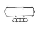 Jeep Valve Cover Gasket
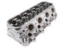 Jeep Cylinder Head
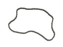 Jeep Timing Chain
 Jeep Timing Cover
 Jeep Transmission Mount
 Jeep Engine Mount Bracket
 Jeep Crankshaft Thrust Washer
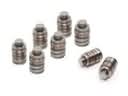 Jeep Lash Adjuster
 Jeep Oil Pump Gasket
 Jeep Pushrod
 Jeep Timing Belt Idler Pulley
 Jeep Timing Chain Guide