JeepParts
My Garage
My Account
Cart
OEM Jeep Liberty Rod Bearing
Engine Connecting Rod Bearing- Select Vehicle by Model
- Select Vehicle by VIN
Select Vehicle by Model
orMake
Model
Year
Select Vehicle by VIN
For the most accurate results, select vehicle by your VIN (Vehicle Identification Number).
3 Rod Bearings found


Jeep Liberty Bearings Part Number: 5174612AA
$14.57 MSRP: $24.10You Save: $9.53 (40%)


Jeep Liberty Bearings Part Number: 68052222AB
$18.13 MSRP: $26.80You Save: $8.67 (33%)Ships in 1-2 Business Days
Jeep Liberty Bearings Part Number: 68146570AA
Jeep Liberty Rod Bearing
Choose OEM Rod Bearing that meet Jeep factory standards. Jeep designs and tests every component for precision and durability. Each Rod Bearing follows strict manufacturing steps to lock in quality and fit. If your Jeep Liberty matters to you, OEM parts make the smart choice. You'll get the exact look, feel, and performance you expect. Shop genuine Liberty parts at the highly competitive prices online. Enjoy a manufacturer's warranty, a hassle-free return policy, and rapid delivery. No more guesswork with off brands. Get genuine parts with exact fit and true factory performance. Shop with confidence today at JeepPartsDeal.com.
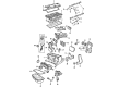
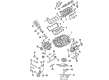
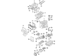
Jeep Liberty Rod Bearing is one of the crucial parts that make a huge difference and has great potential to improve the working capacity of Jeep Liberty cars manufactured between 2002 and 2012. This is a Rod Bearing to the crankshaft and the connecting rods; it helps the crankshaft to rotate with very little friction from the connecting rods which are crucial to the engine's performance. Jeep Liberty has had the KJ and KK generations, and all of them applied different types of Rod Bearings, and the bi-metal and tri-metal ones are notable for their special features. Bi-metal bearings are made with a metallic lining of aluminum alloy to increase its hardness whereas tri-metal bearings offer high strength and fatigue resistance that is suitable for high performance equipment. Proper oil clearance is set to be in the range of 0.001 inches up to 0.0035 inches so as to enhance durability and performance of the Jeep Liberty's engine. The Jeep Liberty Rod Bearing although enjoys the benefit of boosting the engine performance, it is also instrumental in increasing the safety that comes with better stability and control. As a result of the unique and configurable characteristics of the engines designed for high power outputs like oil passage designs, these Rod Bearings are unique in the automotive market. Their compatibility with various Jeep Liberty makes it possible for drivers to depend on their cars for regular use as well as for off-road use if desired. In summary, the Jeep Liberty Rod Bearing is a perfect example of Jeep's reliable and powerful brand; it is, therefore, a vital part to any Jeep Liberty car to enhance its efficiency and safety.
Jeep Liberty Rod Bearing Parts and Q&A
- Q: How to Maintain and Fix a Rod Bearing on Jeep Liberty?A:First, use Plastigage to check the clearance inside the connecting rod bearing and do not use the same bolts to secure the bearing. Apply oil from the engine lubricant to the old threads before you put in your new bolts. Tighten each bolt just enough for it to hold and then torque them with alternating hands to correctly join the cap. Screw each bolt until you reach 27 Nm (20 ft. lbs.) extra 1/4 turn without using a torque wrench for this step. Also, verify the clearing between the connecting rod and cylinder wall with a feeler gauge.
- Q: How to Inspect and Replace Rod Bearings to Ensure Proper Alignment and Clearance on Jeep Liberty?A:Check the rod bearings for signs of scoring, worn patterns, grooving, fatigue and pitting and change those that are worn unusually. Make sure there are no scoring, nicks or burrs on the journals for the connecting rods, because little issues with their proper alignment can harm the Pistons, piston rings, cylinder walls, their bearing and the crankshaft journals. Should unusual wear or damage hint at a misalignment, examine the connecting rod to be sure it is vertically aligned and correct any bent or twisted rods with replacements. Clean excess oil from the connecting rod journal, grease the upper bearing insert and then insert it into the rod, centered in place. With the piston ring compressor and Special Tool 8507, put in the rod and piston assemblies so that the slots of the oil slinger are on the facing edge of the engine and the F's on the piston show the way the engine starts. Put the lower bearing insert into the bearing cap so it is centered and then lay a Plastigage strip over its whole length at the center. Set the cap and connecting rod on the journal and use 27 Nm (20 ft. lbs.) on each bolt, loosening them by a 90-degree turn without moving the crankshaft to keep the Plastigage clean. Measuring the width of the compressed Plastigage gives you the clearance between the bearing and the journal, then you should check that distance against the engine's specifications. If the clearance is good, unmount the Plastigage and install the bearings; if it is beyond spec, replace the bearings and remember to replace the connecting rod bolts every time. Test the plastigage measurement a second time to confirm the correct bearing and after selecting, fit the insert and the cap, securing everything with tightened bolts at 27 Nm (20 ft. lbs.) plus a 90-degree turn. Finally, insert a suitable feeler gauge between the connecting rod and crankshaft journal flange, checking to see if the side clearance meets what the engine requires and change the connecting rod if it is over or under specification.


Related Jeep Liberty Parts
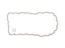 Jeep Liberty Oil Pan Gasket
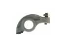 Jeep Liberty Rocker Arm
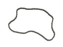 Jeep Liberty Timing Chain
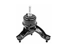 Jeep Liberty Transmission Mount
 Jeep Liberty Balance Shaft Chain
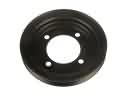 Jeep Liberty Crankshaft Pulley
 Jeep Liberty Cylinder Head Gasket
 Jeep Liberty Exhaust Valve
 Jeep Liberty Motor And Transmission Mount
 Jeep Liberty Piston Ring Set
 Jeep Liberty Timing Belt Tensioner
 Jeep Liberty Valve Stem Seal