JeepParts
My Garage
My Account
Cart
OEM Chrysler Cirrus Axle Shaft
Car Axle Shaft- Select Vehicle by Model
- Select Vehicle by VIN
Select Vehicle by Model
orMake
Model
Year
Select Vehicle by VIN
For the most accurate results, select vehicle by your VIN (Vehicle Identification Number).
6 Axle Shafts found

Chrysler Cirrus Axle Shaft Part Number: R2073683AC

Chrysler Cirrus Axle Shaft Part Number: R2073673AC

Chrysler Cirrus Axle Shaft, Front Part Number: 5017655AA

Chrysler Cirrus Axle Shaft, Front Part Number: 5017656AA
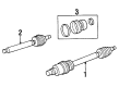
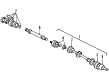
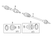
Chrysler Cirrus Axle Shaft
Choose OEM Axle Shaft that meet Chrysler factory standards. Chrysler designs and tests every component for precision and durability. Each Axle Shaft follows strict manufacturing steps to lock in quality and fit. If your Chrysler Cirrus matters to you, OEM parts make the smart choice. You'll get the exact look, feel, and performance you expect. Shop genuine Cirrus parts at the highly competitive prices online. Enjoy a manufacturer's warranty, a hassle-free return policy, and rapid delivery. No more guesswork with off brands. Get genuine parts with exact fit and true factory performance. Shop with confidence today at JeepPartsDeal.com.
The role of Axle Shaft in Chrysler Cirrus cars is to link the differential at the back and transmit power to the drive wheels which has to rotate in opposite directions to enhance the grip of the tires on the road during the cornering system. Usually made of strong metal, such as steel, these axle shafts are expected to adapt to various stress during vehicle use while at the same time ensuring proper positioning and carrying the weight of the car wheels. All Chrysler Cirrus models currently in the market employ halfshafts for power transmission where the splined ends engage the differential and wheel hubs. This design is effective in power transfer in vehicles with independent suspension system. For years, the designs of the axle shafts must perhaps have changed but the purpose has remained nearly the same across all versions of Chrysler Cirrus. Therefore, the wear and tear of the 21694859 leads to noise, vibrations and in extreme situation, failure of Axle Shaft system hence necessitates the need for regular maintenance.
Chrysler Cirrus Axle Shaft Parts and Q&A
- Q: How to Remove and Reinstall an Axle Shaft on Chrysler Cirrus?A:To take out the axle shaft, first slacken the stub axle to hub/bearing nut so it doesn't move and only after you have applied the brakes to the car, start to loosen the hub nut by hand. Place the vehicle on jack stands or a frame contact hoist, then remove the set of front tires and wheels. After that, undo the driveshaft-to-hub and bearing retaining nut and lift out the Brake Caliper assembly, using guide bolts to loosen it and hooking the brackets to keep the brake hoses from being taut as you lift the brake caliper from the Steering Knuckle. Start by taking off the braking disc from the front hub; next, remove the nut securing the outer Tie Rod End from the steering knuckle, holding the rod end stud with an 11/32 socket. The tie rod end stud can be taken out of the steering knuckle arm using Special Tool MB-991113. Should the vehicle have antilock brakes, unscrew the speed sensor cable routing bracket from the steering knuckle. Eliminate both the cotter pin and the castle nut from the end of the lower Ball Joint stud. While detaching them, be sure there is no tool in between the steering knuckle and the joint. Push the steering knuckle outward, strike the nearby boss using a hammer and unfasten the stud from the ball joint while avoiding harm to the lower control arm and seal. Free the steering knuckle from the outer C/V joint and then hold the outer end of the driveshaft. Then use a pry bar to disengage the retaining ring from the tripod joint opposite the transaxle. Hold the connecting piece and inner tripod joint with your hand, then pull out the inner tripod joint directly from the transaxle, but not across the edge of the oil seal. Before you mount the tripod joint, clean the spline area, use a little transmission lubricant and slide it into the transaxle side gear with your hands. Shove the tripod joint into the side gear until the snap ring locks and you cannot remove it by hand. Wipe dirt and moisture from the steering knuckle area near the outer C/V joint and carefully slide the driveshaft into the front hub, then connect the steering knuckle on the stud. Fit the castle nut onto the ball joint stud and tighten it to 95 Nm (70 ft. lbs.). On cars using antilock brakes, attach the speed sensor cable to the steering knuckle and tighten its bolt securely. Attach the tie rod end to the steering knuckle, tighten the bolt to 61 Nm (45 ft. lbs.) with the stud held in place and then place the braking disc back on the hub and bearing assembly. Slide the top part of the caliper under the top abutment, push the bottom down again the bottom abutment and tighten the bolts to 31 Nm (23 ft. lbs.). Clean any dirt from the outside of the C/V joint stub axle, fit the hub nut in place and tighten it. When the vehicle brakes are activated, apply 142 Nm (105 ft. lbs.) of pressure to tighten the hub nut. Install the front wheel and tire assembly, fastening the lug nuts with a tightness of 135 Nm (100 ft. lbs.), drive the vehicle down, check the transaxle fluid and adjust the front toe to its proper specification.

Related Chrysler Cirrus Parts
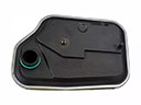 Chrysler Cirrus Automatic Transmission Filter
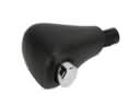 Chrysler Cirrus Automatic Transmission Shift Levers
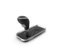 Chrysler Cirrus Automatic Transmission Shifter
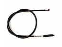 Chrysler Cirrus Clutch Cable
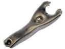 Chrysler Cirrus Clutch Fork
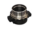 Chrysler Cirrus Clutch Release Bearing
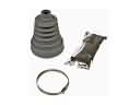 Chrysler Cirrus CV Boot
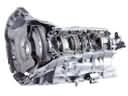 Chrysler Cirrus Transmission Assembly
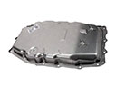 Chrysler Cirrus Transmission Pan
Browse Chrysler Cirrus Axle Shaft by Years
2000
1999
1998
1997
1996
1995