JeepParts
My Garage
My Account
Cart
OEM Chrysler Cirrus Rack And Pinion
Steering Gear- Select Vehicle by Model
- Select Vehicle by VIN
Select Vehicle by Model
orMake
Model
Year
Select Vehicle by VIN
For the most accurate results, select vehicle by your VIN (Vehicle Identification Number).
4 Rack And Pinions found

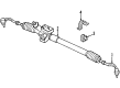
Chrysler Cirrus Steering Gear Part Number: 4883864AA
Chrysler Cirrus Steering Gear Part Number: 4897582AB
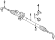
Chrysler Cirrus Steering Gear Part Number: 4886335AA

Chrysler Cirrus Steering Gear Part Number: 4897585AB
Chrysler Cirrus Rack And Pinion
Choose OEM Rack And Pinion that meet Chrysler factory standards. Chrysler designs and tests every component for precision and durability. Each Rack And Pinion follows strict manufacturing steps to lock in quality and fit. If your Chrysler Cirrus matters to you, OEM parts make the smart choice. You'll get the exact look, feel, and performance you expect. Shop genuine Cirrus parts at the highly competitive prices online. Enjoy a manufacturer's warranty, a hassle-free return policy, and rapid delivery. No more guesswork with off brands. Get genuine parts with exact fit and true factory performance. Shop with confidence today at JeepPartsDeal.com.
On the Chrysler Cirrus, steering is delivered using a Rack And Pinion and pinion which transfers the circular or rotational movement of the steering wheel directly to the turning movement of the front wheels. This particular type of track and rack system relies on gears that are housed within a chassis and with the rack gear being linked to tie-rod that will turn the wheels. Power-assisted rack and pinions are commonplace in Cirrus vehicles and typically such automobiles bear hydraulic systems for pressurized fluid supply to the steering. It is normal to have steer rack leakage because the seals or the hoses got bad; gear issues leading to rubbery, unresponsive, or erratic steering. If a car's steering wheel has too much dead-in, shakes in its position, or pull the car to either side, it might be high time to replace the rack and pinion for precise and accurate steering.
Chrysler Cirrus Rack And Pinion Parts and Q&A
- Q: How to Remove and Install a Rack and Pinion Steering Gear Assembly on Chrysler Cirrus?A:Get rid of the remote ground cable by unplugging it from the shock tower first and then isolate it with an isolator. Suck out as much power steering fluid from the remote tank as you can and then straighten the Steering Wheel and front wheels, locking the wheel. From under the instrument panel, take off the "E" clip and pinch bolt from the rack and pinion shaft linkage on early vehicles. On later models, just slide the intermediate shaft off the rack and pinion shaft. Raise the car, remove the wheels and tires from the front and then remove the outer ends of the tie rod from the steering using a socket and screw. To change the Tie Rod End studs, use the Special Tool MB-991113 to remove them. Put marks on the crossmember and on the body where it will fit together before you remove the crossmember. Detach the bushing clamp nuts, use a wire to keep the antilock brakes unit supported and unlink the crossmember from the front suspension. Start by removing the under engine support bracket, then the front bolts holding the shock absorber clevis clips to the crossmember and then the bolts from the rear support bracket and the engine bracket to the transaxle mounting bracket. Reduce the front suspension crossmember enough with the transmission jack that you can remove the rack and pinion safely and without it hanging on the lower control arms. Disconnect the power steering fluid hoses and the wiring harness connector from the rack and pinion. Afterward, remove the bolts that connect the assembly to the crossmember. While putting in an updated rack and pinion, take over the required parts from the old system. To install, set the rack and pinion on the front suspension crossmember and attach it securely with the right bolts, tightened to 68 Nm (50 ft. lbs.). Join the power steering fluid lines, tightening them to 31 Nm (275 inch lbs.) and clamp the front suspension crossmember into place, so it lines up with the marks seen earlier. Tighten each mounting bolt to a force of 2 Nm (20 inch lbs.) to hold it all in place and then gently push the crossmember into the right place. Torque each rear and front bolt you put in to a strength of 163 Nm (120 ft. lbs.). Secure the engine support bracket loosely, attach the rear support bracket and fit each bolt with 75 Nm (55 ft. lbs.) of torque. Put the harness back into the power steering fluid pressure switch and seat the antilock brakes hydraulic control unit. Fit the shock absorber clevis loosely on the lower control arm and attach the tie rod end onto the Steering Knuckle, tightened to 61 Nm (45 ft. lbs.). Attach the stabilizer bar bushing clamp tightly, raise the vehicle, lower it again and tighten the shock absorber clevis bolt to the indicated torque of 92 Nm (68 ft. lbs.). Put in the wheel and tire assemblies and tighten the nuts to a torque of 129 Nm (95 ft. lbs.). Secure the intermediate shaft onto the rack and pinion shaft, center the steering wheel and use the proper torque for the pinch bolt on each model. Take away the steering wheel holder, stop at the correct fluid level in the reservoir, start the engine for pumping and look for any leaks. When done, raise just the front wheels, bleed the steering, gently lower the wheels, check front alignment, set the Toe and tighten the tie rod jam nut to 74 Nm (55 ft. lbs.). Fix the rack and pinion to the tie rod boots when required.

Related Chrysler Cirrus Parts
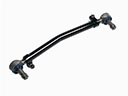 Chrysler Cirrus Drag Link
 Chrysler Cirrus Power Steering Cooler
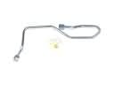 Chrysler Cirrus Power Steering Hose
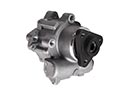 Chrysler Cirrus Power Steering Pump
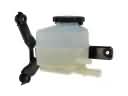 Chrysler Cirrus Power Steering Reservoir
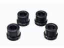 Chrysler Cirrus Rack & Pinion Bushing
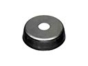 Chrysler Cirrus Radius Heat Shield
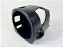 Chrysler Cirrus Steering Column Cover
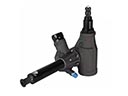 Chrysler Cirrus Steering Gear Box
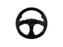 Chrysler Cirrus Steering Wheel
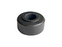 Chrysler Cirrus Tie Rod Bushing
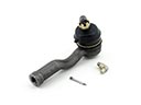 Chrysler Cirrus Tie Rod End