JeepParts
My Garage
My Account
Cart
OEM Chrysler Timing Chain
Engine Timing Chain- Select Vehicle by Model
- Select Vehicle by VIN
Select Vehicle by Model
orMake
Model
Year
Select Vehicle by VIN
For the most accurate results, select vehicle by your VIN (Vehicle Identification Number).
22 Timing Chains found


Chrysler Timing Chain Part Number: 5047366AA
$115.57 MSRP: $170.00You Save: $54.43 (33%)Product Specifications- Other Name: Chain - Timing; Chain Timing


Chrysler Timing Chain Part Number: 4884868AC
$68.35 MSRP: $103.00You Save: $34.65 (34%)Product Specifications- Other Name: Chain - Timing; Engine Timing Chain; Chain Timing


Chrysler Timing Chain Part Number: 5184355AF
$34.43 MSRP: $50.85You Save: $16.42 (33%)Ships in 1-3 Business DaysProduct Specifications- Other Name: Chain - Timing Primary; Engine Timing Chain; Chain Timing Primary
- Replaces: 5184355AE


Chrysler Timing Chain Part Number: 5184352AF
$147.90 MSRP: $259.00You Save: $111.10 (43%)Ships in 1-3 Business DaysProduct Specifications- Other Name: Chain - Timing Secondary; Engine Timing Chain; Chain Timing Secondary
- Replaces: 5184352AE


Chrysler Timing Belt Part Number: 4663635
$141.63 MSRP: $209.00You Save: $67.37 (33%)Product Specifications- Other Name: Chain - Timing; Engine Timing Chain; Timing Chain; Chain Timing


Chrysler Timing Chain Part Number: 53020444
$37.28 MSRP: $54.80You Save: $17.52 (32%)Ships in 1-2 Business DaysProduct Specifications- Other Name: Chain - Timing; Engine Timing Chain; Chain, Timing; Chain Timing


Chrysler Timing Chain Part Number: 4884870AB
$50.62 MSRP: $74.35You Save: $23.73 (32%)Ships in 1-2 Business DaysProduct Specifications- Other Name: Chain - Balance Shaft; Engine Oil Pump Chain; Chain; Chain Balance Shaft


Chrysler Timing Chain Part Number: 4663674AD
$40.34 MSRP: $57.20You Save: $16.86 (30%)Ships in 1-2 Business DaysProduct Specifications- Other Name: Chain - Timing Secondary; Engine Timing Chain; Chain; Chain Timing Secondary; Chain Timing
- Replaces: 4663674, 4663674AC


Chrysler Timing Chain Part Number: 4740275
$56.14 MSRP: $71.16You Save: $15.02 (22%)Ships in 1-2 Business DaysProduct Specifications- Other Name: Chain - Timing; Engine Timing Chain; Chain, Timing - Silent; Chain Package Timing; Chain, Timing


Chrysler Timing Chain Part Number: 4892349AA
$276.65 MSRP: $315.00You Save: $38.35 (13%)Ships in 1-2 Business DaysProduct Specifications- Other Name: Chain - Timing Primary; Engine Timing Chain; Chain Timing Primary; Chain Timing

Chrysler Timing Chain Part Number: 5047907AA
$41.74 MSRP: $84.60You Save: $42.86 (51%)Ships in 1-2 Business DaysProduct Specifications- Other Name: Chain - Timing Primary; Engine Timing Chain; Chain Timing Primary
Chrysler Timing Chain Part Number: 5047963AB
$71.36 MSRP: $107.00You Save: $35.64 (34%)Product Specifications- Other Name: Chain - Timing Secondary; Engine Timing Chain; Chain Timing Secondary
- Replaces: 5047963AA

Chrysler Timing Chain Part Number: 4666059AA
$49.99 MSRP: $73.50You Save: $23.51 (32%)Ships in 1-2 Business DaysProduct Specifications- Other Name: Chain - Timing; Engine Timing Chain; Chain Timing

Chrysler Chain Part Number: 4663674AF
$64.67 MSRP: $73.15You Save: $8.48 (12%)Ships in 1-2 Business DaysProduct Specifications- Other Name: Chain - Timing Secondary; Engine Timing Chain; Chain Timing Secondary; Timing Chain


Chrysler Timing Chain Part Number: 53022316AC
$65.71 MSRP: $96.70You Save: $30.99 (33%)Product Specifications- Other Name: Chain - Timing; Engine Timing Chain; Chain Timing


Chrysler Timing Chain Part Number: 83507095
Product Specifications- Other Name: Sprocket Package - Timing; Engine Timing Chain Kit; Timing Gear; Gear Assembly; Timing Gear Set; Includes Cam And Crankshaft Sprockets; Chain, Timing


Chrysler Timing Chain Part Number: 5098404AA
Product Specifications- Other Name: Chain - Timing; Engine Timing Chain; Chain Timing

Chrysler Timing Chain Part Number: 4884868AB
Product Specifications- Other Name: Chain - Timing; Engine Timing Chain; Chain Timing


Chrysler Gear Assembly Part Number: 68001402AA
Product Specifications- Other Name: Chain - Engine Timing; Engine Timing Chain Kit; Timing Drive Package; Includes all parts except bolts and dowel.

Chrysler Chain Part Number: MD172895
Product Specifications- Other Name: Chain Balancer Timing
| Page 1 of 2 |Next >
1-20 of 22 Results
Chrysler Timing Chain
OEM parts sourced directly from Chrysler deliver superior quality, long lasting strength, and a precise fit you can trust. Each item goes through strict quality checks to ensure safety, toughness, and performance that matches your factory equipment. At JeepPartsDeal online shop, you'll get top-quality, budget-friendly OEM Chrysler Timing Chain for your vehicle. We focus on giving you a high standard without pushing up the price. Our full selection of genuine factory products comes backed by the original manufacturer's warranty. You'll love our fast delivery, seamless shopping experience, and convenient return policy, saving you all the hassle.
Chrysler Timing Chain maintains engine beat accuracy, which cuts wasted engine motion to powerful pulls and more pleasurable drives. Chrysler has been striking a balance between daring appearance and practical thinking, taming vibration with Floating Power, shaping airflow with the radical Airflow body, and subsequently inventing the spacious minivan, making it simple and value apparent all the way through the purchase process, which makes the purchase easy and value obvious, the same spirit that echoes through every Timing Chain linking the past with the present. The interior space continued to expand, ride quality became smoother, and clever storage details ensured the family was organized, as Chrysler paid attention to daily needs, reduced unnecessary flash, and invested resources in comfort improvements that made the daily commute and cross-country trip equally comfortable, showing that progress could also look fashionable and still remain friendly without inflating prices or requiring the individual at the helm to have advanced skills. The recent version of Timing Chain in a Chrysler powertrain has teeth on the crankshaft and camshaft that are linked with steel and shake off heat expansion as well as last much longer than rubber belts, ensuring the valve timing remains on schedule mile after mile without the timing changes that empty wallets or patience meters. The Timing Chain short drive arrangement not only saves clatter and lessens the wear on the bearings but also helps liberate a few extra horses, which are experienced by Chrysler drivers as quicker throttle reaction and more reliable low-rev low-speed torque. Since it is hardly ever needed in the normal course of ownership, Timing Chain owners benefit in both lifetime cost and the ability to enjoy the fun of the ride rather than worrying about time-based maintenance clocks.
Chrysler Timing Chain Parts and Q&A
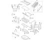
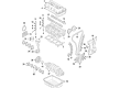
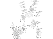
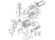
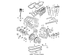
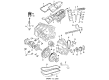
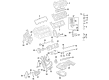
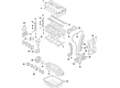
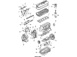
- Q: How to install a Timing Chain on Chrysler Crossfire?A:For installing the timing chain, lift the engine so it hangs down from the engine stand, insert the crankshaft sprocket (2) and align the crankshaft so it's at 40 degrees ATDC. After that, place the balance shaft sprocket next to the timing mark (3) and the copper teeth (1) of the timing chain. Slide the camshaft sprockets (6) into the timing chain so that the marker lines on the sprockets (4) and (5) line up with the timing chain's copper teeth (1). Slide the linked timing chain and sprockets into place and put them inside the timing chain guides (1). Slide in the locking Special Tools 9104 and 9105 and the Camshaft Locating Plates first, then put in the camshaft gear, oil pump, circuit chain (2) and tensioner (1). Set the engine straight up and place the timing chain cover on, fastening it only with the bolts tightened to 20 Nm (15 ft. lbs.). Afterward, take out Special Tools 9104 and 9105 Camshaft Locating Plates from the camshaft sprockets.
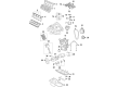
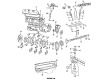
- Q: How to Inspect and Install Timing Chain Sprockets and Guides on Chrysler 300?A:Thoroughly examine sprockets 4, 9, 11 and guides 2, 5, 10. If any are worn, replace them. Always use the relevant guidelines when t lifsracking on a crankshaft sprocket. If you remove them, attach the short chain guides 11 on each side, making sure the bolts are as tight as 28 Nm (250 in. lbs.). Put the crankshaft sprocket's timing mark in line with the mark on the oil pump housing 3 and apply a small amount of engine oil to the timing chain and the guides before installing them. Place the left side primary chain sprocket on the bottom part of the chain so the timing mark is between the two plated timing links 1, then guide the sprocket through the left cylinder head opening downwards. Set the camshaft sprockets to float freely on the camshaft hub, put the left side sprocket onto the camshaft hub loosely and line the time plate link to the crankshaft timing mark 3. Slide the primary chain on to the water pump drive sprocket 11, ensure the timing mark on the right camshaft sprocket is in line with the timing plated link on chain 8 and randomly arrange the chain near the camshaft hub for now. Also, make sure all chain timing plated links are straight to the timing marks found on the sprockets and put in lower chain guide 2 and tensioner arm 5 in the left side, making sure to tighten the mounting bolts to 28 Nm (250 in. lbs.). Before putting in branch pipes, inspect the O-ring in every chain guide access plug and replace if it looks worn. Fix chain guide access plugs to the top of the cylinder heads, using 20 Nm (15 ft. lbs.) of torque. Introduction of engine oil to the tensioner should be prevented by first letting the check ball 2 end of the tensioner drop into the shallow end of Special Tool 8186 3 and depressing the tensioner until the oil is expelled. Slide cylinder plunger 4 into the deeper end of Special Tool 8186 3 and apply pressure until the tensioner releases and hits the top of the same tool to guarantee it is not sticking. Observe the tensioner O-ring 2 for any damage or splits and check that the snap ring 1 is firmly in place and replace it if it is missing. Set the reset chain tensioner 1 in the right cylinder head, put the tensioner retaining plate 2 in place and tighten the bolts to 12 Nm (105 in. lbs.). After choosing the correct cylinder bank, attach 1 (if available) camshaft damper to the specified camshaft hub, then insert a 3/8" square drive extension with a breaker bar into the intake camshaft hub. Turn the camshaft until its hub and the damper holes are matched with the camshaft sprocket. Screw in the sprocket bolts and tighten each of them to 28 Nm (250 in. lbs.). Attach a 3/8" square drive extension and breaker bar to the left side camshaft drive hub and turn it clockwise until the bottom sprocket bolt holes line up for installation with the sprocket attaching bolts secured to 28 Nm (250 in. lbs.). Turn the engine slightly in a clockwise direction if needed to fix any timing chain slack and then lightly press the tensioner arm towards the tensioner so it's activated (extended). Install camshaft position sensor 2 and the electric connector, continue by adding the timing chain cover, crankshaft vibration damper and cylinder head covers and finish with the upper intake manifold. An engine loud sound may happen just after installing a reset tensioner, but it usually clears up after a few seconds. Add coolant to the radiator and attach the negative battery cable to No.1 terminal.


Related Chrysler Parts
 Chrysler Cylinder Head
 Chrysler Oil Filter
 Chrysler Balance Shaft Chain
 Chrysler Camshaft Seal
 Chrysler Coolant Filter
 Chrysler Engine Cover
 Chrysler Harmonic Balancer
 Chrysler Oil Filler Cap
 Chrysler Oil Pan Gasket
 Chrysler Pushrod
 Chrysler Timing Belt Idler Pulley
 Chrysler Valve Guide