JeepParts
My Garage
My Account
Cart
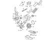
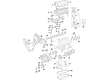
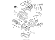
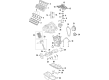
OEM Chrysler Rod Bearing
Engine Connecting Rod Bearing- Select Vehicle by Model
- Select Vehicle by VIN
Select Vehicle by Model
orMake
Model
Year
Select Vehicle by VIN
For the most accurate results, select vehicle by your VIN (Vehicle Identification Number).
31 Rod Bearings found


Chrysler Bearings Part Number: 5174612AA
$14.57 MSRP: $24.10You Save: $9.53 (40%)Product Specifications- Other Name: Bearing - Connecting Rod; Bearing Kit Connecting Rod Standard See Note; Bearing Kit Connecting Rod Standard
- Replaces: 5093448AB, 5012588AA


Chrysler Bearings Part Number: 4884913AB
$2.34 MSRP: $3.55You Save: $1.21 (35%)Ships in 1-2 Business DaysProduct Specifications- Other Name: Bearing - Connecting Rod; Rod Bearing; Bearing Connecting Rod +3 Micron See Note
- Replaces: 1115A151, 4884913AA


Chrysler Connecting Rod Bearing Part Number: 5184111AF
$3.76 MSRP: $5.65You Save: $1.89 (34%)Ships in 1-2 Business DaysProduct Specifications- Other Name: Bearing - Connecting Rod; Rod Bearing; Bearing; Bearings; Bearing Connecting Rod +.003Mm See Note; Bearing Connecting Rod +.003Mm
- Replaces: 5184111AE


Chrysler Bearings Part Number: 4884911AB
$4.79 MSRP: $7.20You Save: $2.41 (34%)Ships in 1-2 Business DaysProduct Specifications- Other Name: Bearing - Connecting Rod; Rod Bearing; Bearing Connecting Rod-3 Micron See Note
- Replaces: 4884911AA, 1115A149


Chrysler Connecting Rod Bearing Part Number: 5184113AF
$3.83 MSRP: $5.65You Save: $1.82 (33%)Ships in 1-2 Business DaysProduct Specifications- Other Name: Bearing - Connecting Rod; Rod Bearing; Bearing; Bearings; Bearing Connecting Rod - .003Mm See Note; Bearing Connecting Rod - .003Mm
- Replaces: 5184113AE


Chrysler Connecting Rod Bearing Part Number: 4893952AA
$10.37 MSRP: $15.40You Save: $5.03 (33%)Ships in 1-3 Business DaysProduct Specifications- Other Name: Bearing - Connecting Rod; Rod Bearing; Bearings; Bearing Connecting Rod Standard
- Replaces: 4893836AA, 68088069AA


Chrysler Connecting Rod Bearing Part Number: 4626657AD
$16.53 MSRP: $24.35You Save: $7.82 (33%)Ships in 1-2 Business DaysProduct Specifications- Other Name: Bearing Package - Connecting Rod; Bearings; Bearing Package Connecting Rod Standard
- Replaces: 4626657AB, 4626657AC


Chrysler Connecting Rod Bearing Part Number: 68362046AA
$16.59 MSRP: $24.55You Save: $7.96 (33%)Ships in 1-2 Business DaysProduct Specifications- Other Name: Bearing Package - Connecting Rod; Rod Bearing; Bearing; Bearings; Bearing Kit Connecting Rod Standard Upper And Lower; Bearing Kit Connecting Rod Standard
- Replaces: 5086003AD, 5086003AC, 5086003AE


Chrysler Bearings Part Number: 5012363AE
$16.87 MSRP: $25.00You Save: $8.13 (33%)Ships in 1-2 Business DaysProduct Specifications- Other Name: Bearing - Connecting Rod; Rod Bearing; Bearing Kit Connecting Rod Standard See Note; Bearing Kit Connecting Rod Standard
- Replaces: 5012363AC, 5012363AD, 5018584AB, 5012363AB


Chrysler Connecting Rod Bearing Part Number: 68002286AC
$18.22 MSRP: $27.05You Save: $8.83 (33%)Ships in 1-3 Business DaysProduct Specifications- Other Name: Bearing Kit - Connecting Rod; Engine Connecting Rod Bearing Set; Connecting Rod Bearing Set; Rod Bearing; Bearings; Bearing Kit Connecting Rod Standard
- Replaces: 68002286AA, 68002286AB


Chrysler Bearings Part Number: 5161294AA
$18.30 MSRP: $27.05You Save: $8.75 (33%)Ships in 1-2 Business DaysProduct Specifications- Other Name: Bearing Kit - Connecting Rod; Bearing Package Connecting Rod Standard: One [1] Upper & One [1] Lower Bearing.
- Replaces: 5012056AA


Chrysler Connecting Rod Bearing Part Number: 68029429AC
$16.02 MSRP: $23.55You Save: $7.53 (32%)Ships in 1-2 Business DaysProduct Specifications- Other Name: Bearing - Connecting Rod; Rod Bearing; Bearing; Bearings; Bearing Kit Connecting Rod Standard
- Replaces: 68029429AB, 68029429AA, 68029429AI, 68060359AA


Chrysler Bearings Part Number: 4884912AB
$18.19 MSRP: $23.55You Save: $5.36 (23%)Product Specifications- Other Name: Bearing - Connecting Rod; Rod Bearing; Bearing Connecting Rod Standard See Note
- Replaces: 1115A150, 4884912AA


Chrysler Rod Bearings Part Number: 2421305
$21.97 MSRP: $27.86You Save: $5.89 (22%)Ships in 1-2 Business DaysProduct Specifications- Other Name: Bearing Package - Connecting Rod; Engine Connecting Rod Bearing; Connecting Rod Bearing Pair; Rod Bearing; Bearings; Connecting Rod Bearing Package, Standard; Includes various connecting rod bearings.


Chrysler Connecting Rod Bearing Part Number: 68207790AA
$6.32 MSRP: $7.70You Save: $1.38 (18%)Product Specifications- Other Name: Bearing Package - Connecting Rod; Rod Bearing; Bearing; Bearings; Bearing Kit Connecting Rod Standard
- Replaces: 5086003AB

Chrysler Connecting Rod Bearing Part Number: 5047638AC
$3.99 MSRP: $6.00You Save: $2.01 (34%)Ships in 1-2 Business DaysProduct Specifications- Other Name: Bearing - Connecting Rod; Rod Bearing; Bearing; Bearings; Bearing Connecting Rod +3 Micron Used For Upper And Lower; Bearing Connecting Rod +3 Micron See Note
- Replaces: 5047638AB


Chrysler Connecting Rod Bearing Part Number: 4893953AA
$9.41 MSRP: $13.95You Save: $4.54 (33%)Ships in 1-2 Business DaysProduct Specifications- Other Name: Bearing - Connecting Rod; Rod Bearing; Bearings; Bearing Connecting Rod - .003Mm; Bearing Connecting Rod - .006Mm
- Replaces: 4893837AA, 68088070AA


Chrysler Connecting Rod Bearing Part Number: 4893951AA
$14.57 MSRP: $15.05You Save: $0.48 (4%)Ships in 1-2 Business DaysProduct Specifications- Other Name: Bearing - Connecting Rod; Rod Bearing; Bearings; Bearing Connecting Rod +.003Mm
- Replaces: 4893835AA, 68088068AA


Chrysler Connecting Rod Bearing Part Number: 5047637AC
$4.58 MSRP: $6.80You Save: $2.22 (33%)Product Specifications- Other Name: Bearing - Connecting Rod; Rod Bearing; Bearing; Bearings; Bearing Connecting Rod Standard Used For Upper And Lower; Bearing Connecting Rod Standard See Note
- Replaces: 5047637AB


Chrysler Connecting Rod Bearing Part Number: 5184112AF
$16.30 MSRP: $23.55You Save: $7.25 (31%)Product Specifications- Other Name: Bearing - Connecting Rod; Engine Connecting Rod Bearing; Connecting Rod Bearing Pair; Rod Bearing; Bearing; Bearings; Bearing Connecting Rod Standard See Note; Bearing Connecting Rod Standard
- Replaces: 5184112AE
| Page 1 of 2 |Next >
1-20 of 31 Results
Chrysler Rod Bearing
OEM parts sourced directly from Chrysler deliver superior quality, long lasting strength, and a precise fit you can trust. Each item goes through strict quality checks to ensure safety, toughness, and performance that matches your factory equipment. At JeepPartsDeal online shop, you'll get top-quality, budget-friendly OEM Chrysler Rod Bearing for your vehicle. We focus on giving you a high standard without pushing up the price. Our full selection of genuine factory products comes backed by the original manufacturer's warranty. You'll love our fast delivery, seamless shopping experience, and convenient return policy, saving you all the hassle.
Chrysler Rod Bearing reduces friction inside the cylinder to allow crankshafts to rotate freely and engines to live longer. Chrysler has demonstrated over the years since 1925 that solid construction, reasonable prices, and straightforward buying can exist without tricks and spangles and have gained credibility on the highways, as well as through the generations. Chrysler applied Floating Power to damp vibration and inspired the airflow design to make cabins feel cooler as the styling remained bold over long highway hauling. With the launch of the pioneering minivan, Chrysler reminded families that spacious access and ingenious seating could be achieved without compromising the ability to handle or the ability to ride comfortably. Chrysler, year after year, pursued mere utility, expansive interiors, and a disposition that kept drivers relaxed and passengers joyful mile after mile, even on rough-surfaced roads in summer heat. Constructed by hardened bi- or trimetal layers, Rod Bearing has a tight clearance of oil, has high heat resistance, and does not score the crankshaft journals during hours of high revs. Punches of throttle that come out of the blue or loads of heavy towing or mountain hiking are flaked off with ease by high fatigue strength. Self-lubricating surfaces make Rod Bearing slick, initial wear falls away, and cold mornings become non-eventful. Properly torqued, Rod Bearing extends the life of the engine and maintains the smooth tone that the drivers of the engine desire during each journey.
Chrysler Rod Bearing Parts and Q&A
- Q: What Precautions Should Be Taken When Fitting Rod Bearings During Assembly on Chrysler 300?A:Assemble all rods on one bank at a time, noting which end came off of each cap when the installation is done. Don't use a punch to make marks on the rods and make sure you don't injure the surfaces where the rods and caps meet to steer clear of engine-related issues. Put the bearing shells in place so that the tangs sit in the machined holes in the rods and caps and check that the upper half of the bearing is lined up with the oil squirt hole in the rod; install the cap with the tangs on the same side. Be sure the maximum taper across a crankshaft journal is 0.015 mm (0.0006 inch) and the maximum out-of-round is 0.010 mm (0.0004 inch). Bearings come in 0.025 mm (0.001 inch) and 0.250 mm (0.010 inch) undersized versions and you should not mix them when replacing both halves; the rods and bearing caps should not be filed either. To measure Main Bearing Clearance and Connecting Rod Bearing Clearance, use plastigage according to what is required. If the threads on the bolts are getting narrow, replace them. You should use careful taps from a hammer and punch to remove the connecting rod bolts, so you don't damage the cracked cap. If some threads on the bolt do not touch the scale while it's held upright, you must change the bolt out. Before the cap goes on, grease its threads with engine oil, tighten each bolt just enough with your fingers, then tighten both nuts equally and bring them up to specification. To check the connecting rod side clearance, place a dial indicator at a fixed part on the engine, line up the probe perpendicularly with the cap being observed and when the connecting rod is moved to the rear, zero the dial indicator. Move the connecting rod to the front limit and read the dial indicator value which you must compare with the specifications. Perform this for every connecting rod as you turn the crankshaft.
- Q: How to measure Rod Bearing Clearances with Plastigage on Chrysler Crossfire?A:Eliminate any oil from the part before checking crankshaft bearing clearances as Plastigage will disappear into it. Then, add a strip of Plastigage across the entire shell at the cap, keeping it around 1/4 in. (6.35 mm) from both the end and the oil holes; if you suspect another area, put Plastigage there as well. Torque the bearing cap bolts to the correct settings, next remove the bearing cap and measure the width of the Plastigage, then locate the band on the scale that matches the width to get clearance in thousandths of a millimeter. Look for changes in the readings when moving from the top to the bottom, since this flag taper and write down all measurements. Always compare the readings from Plastigage to the engine specifications, ensuring you match the right Plastigage to the proper clearance range. After that, fit the right crankshaft bearings to get the proper bearing gaps.


Related Chrysler Parts
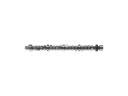 Chrysler Camshaft
 Chrysler Cylinder Head
 Chrysler Oil Pump
 Chrysler Timing Belt
 Chrysler Balance Shaft Chain
 Chrysler Lash Adjuster
 Chrysler Oil Pump Rotor Set
 Chrysler Timing Chain Guide
 Chrysler Timing Cover
 Chrysler Timing Cover Gasket
 Chrysler Transmission Mount
 Chrysler Valve Cover Grommet