JeepParts
My Garage
My Account
Cart
OEM Dodge Stratus Rack And Pinion
Steering Gear- Select Vehicle by Model
- Select Vehicle by VIN
Select Vehicle by Model
orMake
Model
Year
Select Vehicle by VIN
For the most accurate results, select vehicle by your VIN (Vehicle Identification Number).
22 Rack And Pinions found


Dodge Stratus Steering Gear Part Number: 4764920AI
$941.18Ships in 1-2 Business DaysDodge Stratus Steering Gear Part Number: 4764403AE
$211.87 MSRP: $312.00You Save: $100.13 (33%)Ships in 1-3 Business DaysDodge Stratus Steering Gear Part Number: 5093808AA
$219.11 MSRP: $320.00You Save: $100.89 (32%)Ships in 1-3 Business DaysDodge Stratus Steering Gear Part Number: 5093817AA
$224.78 MSRP: $329.00You Save: $104.22 (32%)Ships in 1-3 Business DaysDodge Stratus Gear Assembly Part Number: 4764995AF
$357.24 MSRP: $520.00You Save: $162.76 (32%)Ships in 1-3 Business DaysDodge Stratus Gear Assembly Part Number: 5093819AA
$305.22 MSRP: $447.00You Save: $141.78 (32%)Ships in 1-3 Business DaysDodge Stratus Gear Assembly Part Number: 5093816AA
$356.53 MSRP: $517.00You Save: $160.47 (32%)Ships in 1-3 Business DaysDodge Stratus Gear Assembly Part Number: 5093818AA
$425.23 MSRP: $617.00You Save: $191.77 (32%)Ships in 1-3 Business Days
Dodge Stratus Steering Gear Part Number: MR589197
$142.32 MSRP: $180.42You Save: $38.10 (22%)Ships in 1-2 Business DaysDodge Stratus Gear Assembly Part Number: 4764920AD
$237.93 MSRP: $350.00You Save: $112.07 (33%)
Dodge Stratus Rack Part Number: MR519363

Dodge Stratus Gear Assembly Part Number: MR510121
Dodge Stratus Steering Gear Part Number: MR510120
Dodge Stratus Gear Assembly Part Number: 4879419AB
Dodge Stratus Gear Assembly Part Number: 4764402AD

Dodge Stratus Steering Gear Part Number: 4883864AA
Dodge Stratus Steering Gear Part Number: 4897582AB
Dodge Stratus Steering Gear Part Number: 4886335AA
Dodge Stratus Steering Gear Part Number: 4879419AF

Dodge Stratus Steering Gear Part Number: 4897585AB
| Page 1 of 2 |Next >
1-20 of 22 Results
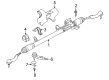
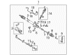
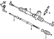
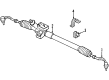
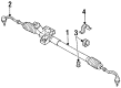
Dodge Stratus Rack And Pinion
Choose OEM Rack And Pinion that meet Dodge factory standards. Dodge designs and tests every component for precision and durability. Each Rack And Pinion follows strict manufacturing steps to lock in quality and fit. If your Dodge Stratus matters to you, OEM parts make the smart choice. You'll get the exact look, feel, and performance you expect. Shop genuine Stratus parts at the highly competitive prices online. Enjoy a manufacturer's warranty, a hassle-free return policy, and rapid delivery. No more guesswork with off brands. Get genuine parts with exact fit and true factory performance. Shop with confidence today at JeepPartsDeal.com.
The Dodge Stratus Rack And Pinion is an important part of the running and operating system of many fabulous Dodge Stratus models with regard to its reliability and other performance factors. This steering mechanism effectively transforms the rotational motion of the steering wheel to the required(turning) motion at the front wheels, making the handling and response smooth. The Dodge Stratus Rack And Pinion is suitable for the first and second generation of the Dodge Stratus, which means that its owners can use this part to ensure their vehicle's prime status. Hydraulic assistance is used in its design and while making the steering easier this feature is also beneficial to general security since the control over the movements is enhanced. The periodic examination of the Dodge Stratus Rack And Pinion is very important mostly because leaks or worn gears of the rack and the pinion, could result to stiff steering and poor handling off the car. The relevance of this component is in the improvement of driving dynamics and possibilities, thus making the driving process more safe and pleasant. Moreover, the Dodge Stratus Rack And Pinion has differentiated features from other cars to meet the market needs in terms of the car's structure, as mentioned above; the rack and pinion design guarantee the logical steering of the car under different situations. Therefore, due to the performances, safety and compatibility of the Dodge Stratus Rack And Pinion, it is still an important tool when it comes to the Dodge Stratus vehicles.
Dodge Stratus Rack And Pinion Parts and Q&A
- Q: How to Remove and Install a Rack and Pinion Steering Gear Assembly on Dodge Stratus?A:Lift the remote ground cable off its mounting stud on the shock tower and attach an isolator to prevent any problems. Empty as much fluid from the remote reservoir as you can and then place the Steering Wheel and front wheels straight, putting the lock on the steering wheel. Open the pinch bolt to release the intermediate shaft from the rack and pinion shaft and pull it off. Putting the vehicle on jack stands or a hoist, you need to take off the front wheel and tire assemblies. Hold the Tie Rod End stud with a 11/32 socket and rotate the nuts clockwise to take them off. You will need Remover, Special Tool MB-991113, to pull out both tie rod end studs from the Steering Knuckles. Make sure to mark on both the crossmember and the truck bed before you remove it so you can put it back in the right place. Release all the clamps binding the stabilizer bar to the body attaching bolts, but make sure the antilock brakes hydraulic control unit is supported by wire if fitted. Pull away the antilock brakes hydraulic control unit from the front suspension crossmember and remove the bolts holding the shock absorber clevis and the under engine support bracket to the same crossmember. Set a transmission jack by the front crossmember, take out the bolts securing it to the frame rails and let the crossmember down just enough to take out the rack and pinion assembly. Take out the power steering fluid pressure hoses and the connector from the switch. Take out the screws securing the rack and pinion and move any needed parts to the fresh rack and pinion. Align the rack and pinion assembly with the front suspension, attach it to the crossmember with its bolts and tighten the bolts firmly to 68 Nm (50 ft. lbs.). Connect both ends of the power steering lines to the pump and the reservoir, holding them tight with what equals 275 inches lbs. With the front suspension crossmember raised, put the rear bolts into the tapping plates and insert the front bolts, tightening all to 2 Nm (20 inch lbs.). Position the crossmember above the previously marked spots and tap it in place. Next, tighten all bolts to 163 Nm (120 ft. lbs.). Secure the engine support bracket by screwing it in with bolts set to 75 Nm (55 ft. lbs.) and then screw in the bolts for the rear support bracket. Correctly connect the wiring harness to the pressure switch for power steering, making sure the secure locking tab is held in place. Fix the antilock brakes hydraulic control unit mounting bracket in place and secure all bolts to a torque of 28 Nm (250 inch lbs.). To loosely install the shock absorber clevis, use bolts and nuts on the lower control arm and attach the tie rod seal boot heat shield and tie rod end into the steering knuckle, holding it with a nut turned to 55 Nm (40 ft. lbs.). After attaching the stabilizer bar bushing clamp to the body in place using the bolts, lower the vehicle, making sure weight comes from the lower control arm. Secure the shock absorber clevis to the control arm bushing with 92 Nm (68 ft. lbs.) and then tighten the wheel and tire assemblies with 129 Nm (95 ft. lbs.). Attach the intermediate shaft back to the rack and pinion shaft, ensuring the edges match and then tighten the new pinch bolt to 44 Nm or 32 ft. lbs. Take off the steering wheel holder, top off the fluid in the power steering pump reservoir and begin the Power Steering Pump Initial Operation process. Check and see if there are any leaks, verify the front alignment, set the front toe and make sure you tighten the ratchets holding the tie rods to 74 Nm (55 ft. lbs.). Straighten the tie rods to the rack and pinion making sure the boots are open and not pinched at the tie rod ends.
- Q: How to Service and Repair a Rack and Pinion Steering System on Dodge Stratus?A:First, pull out the remote ground cable from the left shock tower's ground stud and keep it separate from the vehicle. Drain the remote power steering fluid reservoir as much as it will allow. Move the Steering Wheel and both front wheels straight and clip the locking pin into the steering wheel. Get rid of the pinch bolt and move the intermediate shaft clear of the rack and pinion shaft to disconnect them. Remove the vehicle from the ground and come out with both front wheel and tire assemblies along with the bolts on the splash shield to the crossmember. Using MB-991113, Special Tool, remove the nuts from the outer Tie Rod Ends and pull out the tie rod end studs. Put lines on the body where the suspension crossmember sits, along both depth and side directions, for correct alignment. Unbolt the stabilizer bar bushings from the body, take off the clevis bolts from the shocks, remove the bolts from the engine torque mount, screw out the heat shields near the rack and pinion, remove the power steering pressure hose screws and discard the brake tube routing bracket. Unplug the fuel tube bundle routing support and use a transmission jack to hold the front suspension crossmember as you go. Remove the bolts linking the front suspension crossmember to the frame rails and then successfully lower it enough to remove the power steering rack and pinion. Mix together the power steering pressure and return hoses, pull out the connector from the power steering fluid pressure switch and remove the bolts holding the rack and pinion to the crossmember. Split your parts between the existing gear and your new one, if needed. Gently apply lubricant to the bushing, install it in the rack and pinion mount and then set the sleeve into place. Connect the rack and pinion to the front suspension crossmember and attach it using all four tightened bolts which should be torqued to 68 Nm (50 ft. lbs.). Attach the pump and return hoses to the reservoir and tighten them by hand to 275 inch lbs. Raise up both the front suspension crossmember and rack and pinion so they are against the body and match the marks already drawn. After putting in and tightening the bolts to 163 Nm (120 ft. lbs.), lift the transmission jack until it is held by the car. Join together the tubes for the fuel bundle, place the bracket for routing the brake tubes and nail the clamps for the steering hose to the crossmember. Secure the rack and pinion heat shield and the engine torque mount bolts, using 65 Nm (48 ft. lbs.). Loose the shock absorber clevis-to-lower Control Arm bolts and fit the tie rod end into the Steering Knuckle by tightening it with a crowfoot and socket to 55 Nm (40 ft. lbs.). Tighten the stabilizer bar bushing clamp-to-body bolts to 61 Nm (45 ft. lbs.) and put back the drive-belt splash shield. Put a jack stand under the lower arm and not under the ball joint cap, then slowly lower your vehicle until it is supported by the stand. Secure the clevis-to-lower control arm bolts tighten them up to 92 Nm (68 ft. lbs.), then take out the jack stands and place the wheel and tire assemblies in position, tightening the wheel nuts in a crisscross pattern to 135 Nm (100 ft. lbs.). Place the intermediate shaft's splines alongside the rack and pinion shaft, install the new coupling pinch bolt and tighten it to 44 Nm (32 ft. lbs.). Pull the steering wheel holder out, add liquid to the power steering pump and do the Power Steering Pump Initial Coloring. Look for leaks, lower the vehicle and align the front wheels by tightening both tie rod jam nuts to 74 Nm (55 ft. lbs.).


Related Dodge Stratus Parts
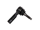 Dodge Stratus Tie Rod
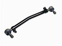 Dodge Stratus Drag Link
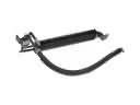 Dodge Stratus Power Steering Cooler
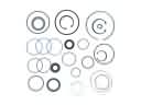 Dodge Stratus Power Steering Gear Seal
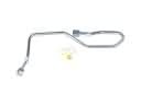 Dodge Stratus Power Steering Hose
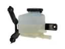 Dodge Stratus Power Steering Reservoir
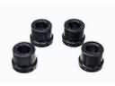 Dodge Stratus Rack & Pinion Bushing
 Dodge Stratus Rack and Pinion Boot
 Dodge Stratus Radius Heat Shield
 Dodge Stratus Steering Gear Box
 Dodge Stratus Tie Rod Bushing
 Dodge Stratus Tie Rod End