JeepParts
My Garage
My Account
Cart
OEM Jeep Wrangler Piston
Engine Pistons- Select Vehicle by Model
- Select Vehicle by VIN
Select Vehicle by Model
orMake
Model
Year
Select Vehicle by VIN
For the most accurate results, select vehicle by your VIN (Vehicle Identification Number).
12 Pistons found


Jeep Wrangler Piston Part Number: 4666129AA
$227.63 MSRP: $347.00You Save: $119.37 (35%)Ships in 1-2 Business Days

Jeep Wrangler Connecting Rod Part Number: 68090672AA
$291.72 MSRP: $439.00You Save: $147.28 (34%)

Jeep Wrangler Vibration Damper Part Number: 5142303AB
$56.55 MSRP: $81.25You Save: $24.70 (31%)Ships in 1-3 Business Days
Jeep Wrangler Connecting Rod Part Number: 68090673AA
$288.41 MSRP: $435.00You Save: $146.59 (34%)
Jeep Wrangler Piston Part Number: 4798329AC
$138.85 MSRP: $200.00You Save: $61.15 (31%)Ships in 1-2 Business Days
Jeep Wrangler Piston Part Number: 68086046AB
$122.02 MSRP: $134.00You Save: $11.98 (9%)Ships in 1-2 Business Days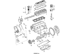
Jeep Wrangler Piston Part Number: 4897013AA
Jeep Wrangler Piston Part Number: 4897012AA
Jeep Wrangler Piston Part Number: 4897011AA
Jeep Wrangler Piston Part Number: 4897010AA

Jeep Wrangler Piston Part Number: 4773568
Jeep Wrangler Piston Part Number: 4798332AC
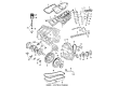
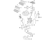
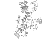
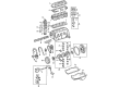
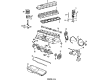
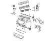
Jeep Wrangler Piston
Choose OEM Piston that meet Jeep factory standards. Jeep designs and tests every component for precision and durability. Each Piston follows strict manufacturing steps to lock in quality and fit. If your Jeep Wrangler matters to you, OEM parts make the smart choice. You'll get the exact look, feel, and performance you expect. Shop genuine Wrangler parts at the highly competitive prices online. Enjoy a manufacturer's warranty, a hassle-free return policy, and rapid delivery. No more guesswork with off brands. Get genuine parts with exact fit and true factory performance. Shop with confidence today at JeepPartsDeal.com.
In Jeep Wrangler vehicles, the piston is used to form part of the internal combustion engine through which the force created through the combustion of fuel is translated to mechanical force to for the movement of the vehicle. The Jeep Wrangler piston is intended to sustain pressure and heat, enhance the vehicle through such features like the cooling cavities which is supplied with oil. In Jeep Wrangler engines, various kinds of pistons have been used for many years, such as trunk pistons that are used in both petrol and diesel engine and they are capable of withstanding side forces besides featuring oil rings below the gudgeon pin. Furthermore Jeep has been using other intricate pistons such as slipper pistons in high speed petrol engines the piston is made with light weight, balanced and given refined accuracy. On the other hand, crosshead pistons have been applied in large slow speed diesel engines of Jeep Wrangler to give it side support and help improve the oil lubrication hence reducing the component of friction. Every piston type that has been incorporated in Jeep wrangler models relates to certain types of engines to guarantee optimum performance on distinct terrains.
Jeep Wrangler Piston Parts and Q&A
- Q: How Should You Prepare Pistons and Connecting Rod Assemblies for Bore Installation on Jeep Wrangler?A:Set up the piston and connecting rod so that none of the gaps between compression rings and the oil ring rail are aligned and so that the 'arrow' on top of the piston points to the front of the engine, when possible. Be sure that the oil ring expander ends are touching and that the rail spaces are correct before installing the ring compressor. After greasing the piston and rings with clean engine oil, set a piston ring compressor on the piston and gently tighten it so that the rings stay in the right place. Put the upper bearing over the connecting rod and add oil to it. Fit connecting rod bolt protectors or use tool #8189 for the cracked cap version. Install the piston labeling with an "F" or arrow so that it is positioning toward the front of the engine on both banks, making sure the connecting rod hole is on the side the engine is most likely to be used under load. Turn the Crankshaft clockwise and slide the connecting rod journal into the center of the cylinder until it's all the way in before inserting the connecting rod and piston into the bore with taps from a hammer handle while guiding the rod into position. Once the lower bearing shell is place and the right cap on the connecting rod, attach the connecting rod cap retaining nuts to the rod bolts, clean and oiled and tighten each to 54 Nm (40 ft. lbs.) followed by a further 1/4 turn. At first, tighten each connecting rod bolt to 7 Nm (5 ft. lbs.), then add 21 Nm (15 ft. lbs.) and finally turn each bolt 90 degrees to reach the final required clamping force. Remember to do this for every piston-to-rod combination and after that, put on the cylinder heads and Oil Pan. After that, put the right amount of oil into the engine crankcase and join the negative cable to the battery.
- Q: How to Remove and Replace a Piston in an Engine on Jeep Wrangler?A:First uncover the engine cylinder head cover, take off the Rocker Arms, bridges and pivots, remove the push rods and then remove the engine cylinder head. Slide one piston to the bottom of the stroke, then ream the point where the piston meets the upper part of the wall using a ridge reamer, collecting anything removed by placing a protective cloth around the cylinder. Lift the vehicle, drain the engine oil and only then can you remove both the Oil Pan and its gasket. Afterwards, pull off the connecting rod bearing caps and inserts; then, note the cylinder bore position on them, because the caps are stamped with a letter code. When the vehicle is taken down to about 2 feet from the floor, secure pieces of rubber hose on the bolts to stop them from scratching the crankshaft or cylinder walls. Allow an assistant to push the assembly up through the top opening of the cylinder bores. Use a proper solvent to clean the piston and connecting rod assembly, then look for dangers of excessive wear, taper and damage called scoring on the connecting rod journal, as well as any twisting or bending on the connecting rod. Check for the piston's tapered and elliptical structures, signs of wear around the skirt and signs of damage or wear on the ring lands. Before installing, completely clean the cylinder bore areas, apply a careful film of oil with a clean cloth and wipe properly. If you take out the piston assembly, put on the piston rings and coat them with clean engine oil, making sure the connecting rod bolts are shielded from the crankshaft journals and cylinders by a rubber hose. Make sure the arrow on the piston points toward the front of the engine as you put the connecting rod and piston in through the top of the cylinder bores with the piston ring compressor. Elevate the vehicle and place a bearing insert into every journal to obtain the listed clearance using the various sized bearings shown on the Connecting Rod Bearing Fitting Chart. A rod journal is indicated by a paint mark next to the cheek or counterweight, facing the flange area, giving information about the journal's size. In some applications, different sizes of inserts may be used as a couple and using a smaller insert with one that is only 0.025 mm (0.001 inch) smaller can narrow the space by 0.013 mm (0.0005 inch). Do not use the same bearing cap on several connecting rods, as the number on the oil squirt hole will not match the number stamped on the cylinder. Align the connecting rod caps and inserts on the engine so the squirt holes in the rods look towards the camshaft and the arrows on the pistons point to the front end of the engine. After that, fit the oil pan and gasket, bring the car all the way down and secure the cylinder head, push rods, rocker arms, bridges, pivots and the engine cylinder head cover, filling the crankcase with oil during the final stage.


Related Jeep Wrangler Parts
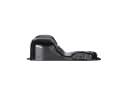 Jeep Wrangler Oil Pan
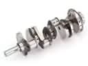 Jeep Wrangler Crankshaft
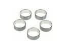 Jeep Wrangler Camshaft Bearing
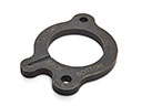 Jeep Wrangler Camshaft Thrust Plate
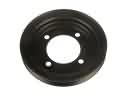 Jeep Wrangler Crankshaft Pulley
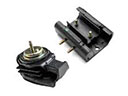 Jeep Wrangler Motor And Transmission Mount
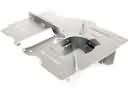 Jeep Wrangler Oil Pan Baffle
 Jeep Wrangler Pushrod
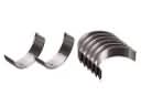 Jeep Wrangler Rod Bearing
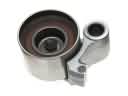 Jeep Wrangler Timing Belt Idler Pulley
 Jeep Wrangler Timing Cover Gasket
 Jeep Wrangler Variable Timing Sprocket