JeepParts
My Garage
My Account
Cart
OEM 2000 Dodge Durango A/C Clutch
Air Conditioning Clutch- Select Vehicle by Model
- Select Vehicle by VIN
Select Vehicle by Model
orMake
Model
Year
Select Vehicle by VIN
For the most accurate results, select vehicle by your VIN (Vehicle Identification Number).
2 A/C Clutches found

2000 Dodge Durango Clutch & Pulley Part Number: 4882008
Product Specifications- Other Name: Clutch - A/C Compressor; A/C Compressor Clutch; Clutch Coil; Clutch; Clutch A/C Compressor
- Item Weight: 6.00 Pounds
- Item Dimensions: 6.8 x 6.6 x 2.1 inches
- Condition: New
- Fitment Type: Direct Replacement
- SKU: 4882008
- Warranty: This genuine part is guaranteed by Mopar's factory warranty.
2000 Dodge Durango Clutch & Pulley Part Number: 5016126AA
Product Specifications- Other Name: Clutch - A/C Compressor; A/C Compressor Clutch; Clutch; Compressor; Clutch A/C Compressor
- Item Weight: 6.50 Pounds
- Condition: New
- Fitment Type: Direct Replacement
- SKU: 5016126AA
- Warranty: This genuine part is guaranteed by Mopar's factory warranty.
2000 Dodge Durango A/C Clutch Parts and Q&A
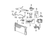
- Q: What Steps Ensure the A/C Clutch Replacement Doesn't Affect the Refrigerant Charge on 2000 Dodge Durango?A: Replacing the compressor clutch, pulley or coil in the car will not drain the refrigerant system. Pull out and isolate the battery's negative cable and then move the serpentine drive belt. Disconnect the connector at the clutch coil wire harness of the compressor. With Special Tool 6462 from Kit 6460, hold the clutch plate still and take out the hex nut while the two pins of the spanner wrench are inserted into the clutch plate's holes. Afterwards, eliminate the clutch plate and shims and slip a snap ring plier beneath the front outer housing snap ring to remove it. Put the lip of Special Tool C-6141-1 from Kit 6460 into the snap ring groove and, on top, place the shaft protector, also Special Tool C-6141-2 in Kit 6460. Use Special Tool C-6461 to attach through-bolts to the puller flange and into the rotor pulley jaws, fully tightening them and turn the center bolt of the puller clockwise until the pulley separates. Unscrew the retainer and screw on the clutch coil lead wire harness on the front housing of the compressor. After that, pull off the snap ring from the compressor hub and remove the clutch field coil. Check both the clutch pulley friction surface and the front plate for abnormal wear or marking and replace them if there is much damage. When the friction surfaces appear to be oily, seek oil on the shaft and nose of the compressor. If the felt pad on the front cover is oily, the shaft seal has leaked, so you need a new compressor. Look for any roughness or unusual grease escaping from the clutch pulley bearing and change it if required. At the beginning of installation, set up the clutch field coil and snap ring. Next, secure the clutch coil lead wire harness retaining clip on the compressor housing and tighten the screw. Make sure the rotor assembly is straight on the hub of the front compressor housing, then use Special Tool 6464 from Kit 6460 for the threading on the driver, Special Tool 6143 from Kit 6460. Slide the driver tool assembly firmly into the bearing hole on the rotor, so that the outer edge touches the rotor bearing's inner face. Press the end of the driver while turning the rotor to keep it from catching until you feel it hit the compressor front housing hub and hear a different sound. Place the outer front rotor snap ring with pliers, with the beveled side outward and the ring's edges seated in the groove to avoid clutch failure. Position the original clutch shims onto the compressor shaft and then, using Special Tool 6141-2, carefully tap the clutch plate down until it seats against the shims and makes a noticeable difference in sound. Install and tighten the compressor shaft hex nut until it reaches a value of 14.4 Nm (10.5 ft. lbs.). Test the clutch at the center and around its edges with a feeler gauge, adding or removing shims to reach the specification of approximately 0.5 mm and by tapping or spacing the shims, ensure the whole circumference is even. When fitting a new clutch to a compressor, always use the first set of shims provided with the assembly or, if replacing an old clutch, insert the 1.0, 0.50 and 0.13-mm shims (0.040, 0.020 and 0.005 inches) from the clutch hardware package. Use the last steps used in uninstalling to return everything to normal in the end. To seat and adjust the clutch properly, conduct twenty short runs of five seconds on and five seconds off, with the heater-A/C control in recirculation, the blower motor at full speed and the engine turning between 1500 and 2000 rpm.
Related 2000 Dodge Durango Parts
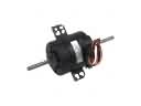 2000 Dodge Durango Blower Motor
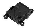 2000 Dodge Durango Blend Door Actuator
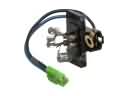 2000 Dodge Durango Blower Motor Resistor
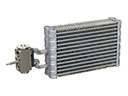 2000 Dodge Durango Evaporator
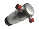 2000 Dodge Durango A/C Accumulator
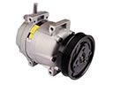 2000 Dodge Durango A/C Compressor
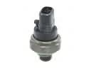 2000 Dodge Durango A/C Compressor Cut-Out Switches
 2000 Dodge Durango A/C Expansion Valve
 2000 Dodge Durango A/C Hose
 2000 Dodge Durango A/C Switch
 2000 Dodge Durango A/C System Valve Core
 2000 Dodge Durango Blower Control Switches