JeepParts
My Garage
My Account
Cart
OEM Chrysler Ball Joint
Control Arm Joint- Select Vehicle by Model
- Select Vehicle by VIN
Select Vehicle by Model
orMake
Model
Year
Select Vehicle by VIN
For the most accurate results, select vehicle by your VIN (Vehicle Identification Number).
10 Ball Joints found


Chrysler Lower Ball Joint, Front Part Number: 5143570AA
$45.84 MSRP: $98.35You Save: $52.51 (54%)Ships in 1-2 Business DaysProduct Specifications- Other Name: Balljoint - Lower Control Arm; Suspension Ball Joint, Front Lower; Ball Joint Package Lower Control Arm; Suspension Ball Joint; Ball Joint
- Position: Front Lower


Chrysler Stabilizer Link, Front Part Number: 4695626
$74.74 MSRP: $81.90You Save: $7.16 (9%)Ships in 1-2 Business DaysProduct Specifications- Other Name: Balljoint - Sway Bar; Front Suspension Stabilizer Bar Link Kit.; Stabilizer Link Joint; Sway Bar Link and Bushing Assembly; Ball Joint Sway Bar.
- Position: Front

Chrysler Ball Joint, Rear Upper Part Number: 4879321AC
$84.12 MSRP: $212.00You Save: $127.88 (61%)Ships in 1-2 Business DaysProduct Specifications- Other Name: Balljoint - Upper Control Arm; Suspension Ball Joint, Front Upper, Rear Upper; Upper Ball Joint; Upper Ball Joints; Ball Joint Upper Control Arm; Suspension Ball Joint
- Position: Rear Upper
- Replaces: 4879225AA, 4879321AB, 4879321AA

Chrysler Ball Joint, Front Lower Part Number: 4656010AE
$70.36 MSRP: $157.00You Save: $86.64 (56%)Ships in 1-2 Business DaysProduct Specifications- Other Name: Ball Join - Lower Control Arm; Suspension Ball Joint, Front; Lower Ball Joint; Ball Joint Kit Lower Control Arm; Ball Joint Lower Control Arm; Suspension Ball Joint
- Position: Front Lower
- Replaces: 4656010AB, 4656010AD, 4656010AC

Chrysler Lower Ball Joint, Front Part Number: 5099237AB
$212.93 MSRP: $280.00You Save: $67.07 (24%)Ships in 1-2 Business DaysProduct Specifications- Other Name: Balljoint - Lower Control Arm; Suspension Ball Joint, Front Lower; Ball Joint Lower Control Arm; Ball Joint
- Position: Front Lower
- Replaces: 5114166AA, 5099237AA


Chrysler Ball Joint, Front Part Number: 68159271AA
$46.40 MSRP: $66.70You Save: $20.30 (31%)Product Specifications- Other Name: Ball Join - Knuckle; Suspension Ball Joint, Front; Lower Ball Joint; Ball Joint Kit Knuckle; Suspension Ball Joint
- Position: Front


Chrysler Lower Ball Joint, Front Part Number: 5090033AB
$53.36 MSRP: $76.70You Save: $23.34 (31%)Product Specifications- Other Name: Balljoint - Lower Control Arm; Suspension Ball Joint, Front; Ball Joint Lower Control Arm; Suspension Ball Joint; Ball Joint
- Position: Front Lower
- Replaces: 5085914AD, 5085914AC, 5090033AA

Chrysler Mopar Ball Joint Part Number: 4364782
Chrysler Upper Ball Joint Part Number: 5015453AA
Product Specifications- Other Name: Balljoint - Upper Control Arm; Suspension Ball Joint; Ball Joint; Upper Ball Joints
- Position: Upper
Chrysler Ball Joint Part Number: 4443405
Product Specifications- Other Name: Ball Joint Package - & Seal; Suspension Ball Joint; Lower Ball Joint; Ball Joint, Front Suspension Steering Knuckle
Chrysler Ball Joint
OEM parts sourced directly from Chrysler deliver superior quality, long lasting strength, and a precise fit you can trust. Each item goes through strict quality checks to ensure safety, toughness, and performance that matches your factory equipment. At JeepPartsDeal online shop, you'll get top-quality, budget-friendly OEM Chrysler Ball Joint for your vehicle. We focus on giving you a high standard without pushing up the price. Our full selection of genuine factory products comes backed by the original manufacturer's warranty. You'll love our fast delivery, seamless shopping experience, and convenient return policy, saving you all the hassle.
Chrysler Ball Joint holds the wheels straight and the steering sharp in each mile of the road. Since the year 1925, Chrysler branded its name on solid vehicles that cut off vibration, airflow shape, and prefer spacious interiors without empty pockets. Chrysler pioneered innovation with Floating Power, which reduced the shaking of the engines, and radical innovation with the Airflow body, which allowed cabins to breathe and ride more smoothly. Subsequently, Chrysler introduced the first minivan, and it was evident that ordinary consumers could easily access convenient seating and a comfortable ride that larger wagons could never provide. Largely over decades, Chrysler continued to perfect interior space, balance of ride, and practical details so the driver and the passengers experience rather than survive the trip. A Ball Joint inside the front suspension connects the control arm with the steering knuckle in a greased socket with a steel stud swiveling to allow the wheel to pivot without losing load or tracking angle in holding the load and tracking angles. A contemporary Ball Joint defeats the out-of-date kingpin since it can be adjusted separately in caster and camber, and this instills sharpness in handling and ensures tires are gripped over bumps. Each Ball Joint is defended by sealed boots against grit and contains lubricant; therefore, steering is smooth, noise remains low, and the suspension endures years of daily wear and tear.
Chrysler Ball Joint Parts and Q&A
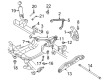
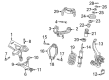
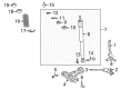
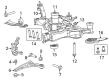
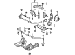
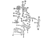
- Q: How to Remove the Front Lower Ball Joint on Chrysler Crossfire?A:First, lift the vehicle and hold up the end with jack stands, then remove the wheel and tire. After that, separate the front disc brake caliper (1) and the front disc brake rotor (1). Removing the front dust shield first requires unscrewing the three hex bolts (1), then the front shock arm bolt (1) and finally the front spring (1). Following that, remove nuts (1 and 2) from the lower ball joint. Never use a pneumatic tool to join the bolt with the special tool. Put Special Tool 9168 Ball Joint Puller (1) on the outer ball joint stud and push it out from the steering knuckle and then attach Special Tool 9168 Ball Joint Puller (2) to the upper ball joint stud and press it out of the lower control arm.
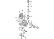
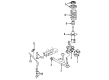
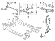
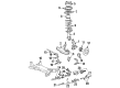
- Q: How to Install a Front Lower Ball Joint on Chrysler Sebring?A:Bend Remover/Installer (5), Special Tool 8441-1, use Installer (2), Special Tool 9964-1, Special Tool 9964-2 and a new ball joint. Then place the ball joint (stem down) into Installer 9964-2. Put the assembly part on the knuckle and hand screw it in. Use a wrench to tighten the screw-drive which forces the ball joint into the knuckle until the ball stops against the bottom of the knuckle. Loose the screw on the shaft and take out the tools, then fit a new snap-ring into the groove of the ball joint using a drift punch. Place the hub and bearing into the knuckle (2) and insert the half shaft outer C/V joint splines onto them so the lower ball joint stud can connect to the mounting hole in the lower control arm. Put in a fresh ball joint stud nut (4) and fasten it to a torque of 95 Nm (70 ft. lbs.). Fasten the wheel speed sensor head (3) to the knuckle (4) using a screw (2) tight to 12 Nm (106 in. lbs.), then fit the routing clip (1) to secure the cable from the wheel speed sensor to the knuckle (4). After that, put in the brake rotor, the disc brake caliper and the adapter. Remove any debris from inside the slot on the half shaft outer C/V joint, then slide on the hub nut (1) and seat it loosely onto the half shaft (2). After a helper fixes the wheels so as not to spin, tighten hub nut (3) to 132 Nm (97 ft. lbs.) Screw the wheel and tire onto the vehicle (1) and tighten the wheel nuts to a torque of 135 Nm (100 ft. lbs.). Setup is complete after the vehicle is lowered and you perform wheel alignment if it is needed.


Related Chrysler Parts
 Chrysler Axle Beam Mount
 Chrysler Axle Shaft Retainer
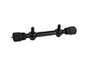 Chrysler Control Arm Shaft Kit
 Chrysler Lateral Link
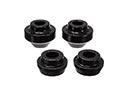 Chrysler Radius Arm Bushing
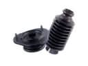 Chrysler Shock and Strut Boot
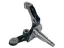 Chrysler Spindle
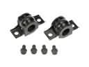 Chrysler Sway Bar Bracket
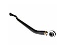 Chrysler Track Bar
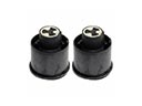 Chrysler Trailing Arm Bushing
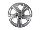 Chrysler Wheel Cover
 Chrysler Wheel Hub