JeepParts
My Garage
My Account
Cart
OEM Chrysler Front Cross-Member
Front Engine Cross Member- Select Vehicle by Model
- Select Vehicle by VIN
Select Vehicle by Model
orMake
Model
Year
Select Vehicle by VIN
For the most accurate results, select vehicle by your VIN (Vehicle Identification Number).
62 Front Cross-Members found


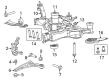
Chrysler Suspension Crossmember, Front Part Number: 68188235AF
$768.30 MSRP: $1130.00You Save: $361.70 (33%)Ships in 1-3 Business DaysProduct Specifications- Other Name: Crossmember - Front Suspension; Suspension Subframe Crossmember, Front; Crossmember; Cradle Front Suspension
- Position: Front
- Replaces: 68188235AG, 68188235AD, 68188235AC, 68188235AE, 68188235AB


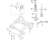
Chrysler Engine Cradle, Front Part Number: 68185029AA
$916.00 MSRP: $1350.00You Save: $434.00 (33%)Ships in 1-3 Business DaysProduct Specifications- Other Name: Crossmember - Front Suspension; Suspension Subframe Crossmember, Front; Crossmember; Crossmember Front Suspension
- Position: Front
- Replaces: 68049475AA, 68049475AD, 68049475AB, 68049475AC


Chrysler Engine Cradle, Front Part Number: 5085819AJ
$698.45 MSRP: $1020.00You Save: $321.55 (32%)Ships in 1-3 Business DaysProduct Specifications- Other Name: Crossmember - Front Suspension; Suspension Subframe Crossmember, Front; Suspension Crossmember; Crossmember; Crossmember Front Suspension
- Position: Front
- Replaces: 5085819AC, 5085819AF, 5085819AG, 5085819AD, 5085819AE, 5085819AH


Chrysler Engine Cradle, Front Part Number: 68204541AB
$1219.43 MSRP: $1790.00You Save: $570.57 (32%)Product Specifications- Other Name: Crossmember - Front Suspension; Suspension Subframe Crossmember, Front; Crossmember; Crossmember Front Suspension
- Position: Front
- Replaces: 68204541AA

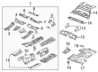
Chrysler Seat Reinforcement, Front Driver Side Part Number: 5096669AA
$3.52 MSRP: $192.00You Save: $188.48 (99%)Ships in 1-2 Business DaysProduct Specifications- Other Name: Crossmember - Front Floor; Seat Track Reinforcement, Left Outer; Floor Pan Crossmember, Left; Floor Crossmember; Crossmember Front Floor
- Position: Front Driver Side
- Replaces: 5134841AA, 5134840AA

Chrysler Floor Crossmember, Front Passenger Side Part Number: 5155114AC
$106.50 MSRP: $225.00You Save: $118.50 (53%)Ships in 1-2 Business DaysProduct Specifications- Other Name: Crossmember - Front Floor; Floor Pan Crossmember, Front Right, Right; Crossmember Front Floor
- Position: Front Passenger Side
- Replaces: 5155114AB

Chrysler Crossmember, Front Part Number: 68232996AD
$97.04 MSRP: $143.00You Save: $45.96 (33%)Ships in 1-3 Business DaysProduct Specifications- Other Name: Crossmember - Floor Pan; Floor Pan Crossmember, Front; Crossmember Floor Pan
- Position: Front

Chrysler Crossmember, Front Center Part Number: 5076416AC
$157.49 MSRP: $232.00You Save: $74.51 (33%)Ships in 1-3 Business DaysProduct Specifications- Other Name: Crossmember - Front Floor; Floor Pan Crossmember, Center, Front; Crossmember Front Floor
- Position: Front Center
- Replaces: 5076416AB
Chrysler Floor Crossmember, Front Driver Side Part Number: 5155115AC
$180.15 MSRP: $265.00You Save: $84.85 (33%)Ships in 1-3 Business DaysProduct Specifications- Other Name: Crossmember - Front Floor; Floor Pan Crossmember, Front Left, Left; Crossmember Front Floor
- Position: Front Driver Side
- Replaces: 5155115AB

Chrysler Front Crossmember Part Number: 5272647AF
$270.79 MSRP: $400.00You Save: $129.21 (33%)Ships in 1-3 Business DaysProduct Specifications- Other Name: Crossmember - Front Frame; Engine Mount Crossmember, Front; Engine Mount Bracket, Front; Engine Mount Crossmember; Fore/Aft Crossmember; Crossmember Front Suspension; Crossmember Front Frame
- Position: Front
- Replaces: 5272647AD, 5272647AE
Chrysler Crossmember, Front Part Number: 68236976AG
$330.84 MSRP: $487.00You Save: $156.16 (33%)Ships in 1-3 Business DaysProduct Specifications- Other Name: Crossmember - Front Suspension; Suspension Subframe Crossmember, Front; Cradle Front Suspension
- Position: Front

Chrysler Rear Crossmember Part Number: 4780800AA
$338.77 MSRP: $499.00You Save: $160.23 (33%)Ships in 1-3 Business DaysProduct Specifications- Other Name: Crossmember - Floor Pan; Floor Pan Crossmember, Rear; Floor Crossmember; Crossmember; Crossmember Floor Pan Rear Kick - Up; Crossmember Floor Pan
- Position: Rear

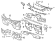
Chrysler Reinforcement, Front Part Number: 68044372AB
$451.13 MSRP: $658.00You Save: $206.87 (32%)Ships in 1-3 Business DaysProduct Specifications- Other Name: Crossmember - Floor Pan; Cowl Panel Reinforcement; Cowl Crossmember, Front; Cowl Reinforcement; Crossmember; Crossmember Floor Pan Toeboard; Crossmember Floor Pan
- Position: Front
- Replaces: 68044372AA


Chrysler Engine Cradle, Front Part Number: 4782700AH
$1028.21 MSRP: $1505.00You Save: $476.79 (32%)Product Specifications- Other Name: Crossmember - Front Suspension; Suspension Subframe Crossmember, Front; Engine Cradle, Front; Suspension Crossmember
- Position: Front
- Replaces: 4782700AC, 4782700AB, 4782700AD, 4782700AG


Chrysler Engine Cradle, Front Part Number: MR554604
Product Specifications- Other Name: Crossmember - Front Suspension; Engine Cradle, Front; Crossmember Front Suspension 2.4L Engine; Crossmember Front Suspension
- Position: Front


Chrysler Upper Tie Bar, Front Part Number: 4805843AK
Product Specifications- Other Name: Crossmember - Front Support; Radiator Support Tie Bar, Front Upper
- Position: Front Upper
- Replaces: 4805843AJ, 4805843AG, 4805843AI, 4805843AH, 5139179AA, 5139179AB, 5139179AC, 4805843AD, 4805843AE, 4805843AF, 5139179AD


Chrysler Crossmember, Front Part Number: 52113572AA
Product Specifications- Other Name: Crossmember - Front Suspension; Torsion Bar Mount, Front; Crossmember Front Suspension
- Position: Front


Chrysler Fore/Aft Crossmember, Front Part Number: 4877087AA
Product Specifications- Other Name: Crossmember - Front Support; Engine Mount Bracket; Frame Crossmember; Motor Mount; Damper; Crossmember; Crossmember Front Suspension; Crossmember Front Support
- Position: Front


Chrysler Engine Cradle, Front Part Number: 4764448AD
Product Specifications- Other Name: Crossmember - Front Suspension; Engine Cradle, Front; Suspension Crossmember; Crossmember Front Suspension
- Position: Front
- Replaces: 4764448AC


Chrysler Engine Cradle, Front Part Number: 5272962AE
Product Specifications- Other Name: Crossmember - Front Suspension; Engine Cradle, Front; Crossmember Front Suspension
- Position: Front
- Replaces: 5272962AD, 5272962AB, 5272962AC
| Page 1 of 4 |Next >
1-20 of 62 Results
Chrysler Front Cross-Member
OEM parts sourced directly from Chrysler deliver superior quality, long lasting strength, and a precise fit you can trust. Each item goes through strict quality checks to ensure safety, toughness, and performance that matches your factory equipment. At JeepPartsDeal online shop, you'll get top-quality, budget-friendly OEM Chrysler Front Cross-Member for your vehicle. We focus on giving you a high standard without pushing up the price. Our full selection of genuine factory products comes backed by the original manufacturer's warranty. You'll love our fast delivery, seamless shopping experience, and convenient return policy, saving you all the hassle.
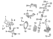
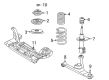
Chrysler Front Cross-Member secures the driving part and ensures that the car remains stable on uneven roads. Chrysler pursued good build quality, reduction of shake through Floating Power and control of airflow into smoother cabins since 1925. Wind went through its Airflow lines and practicality could be stylish in its roomy minivans. The transparency of prices allows families to enter ownership without any ado. Even today Chrysler continues to ride on large interior, fine-tuning of rides and effortless utility that makes the daily commute pain free. Drivers reported that the ride was confident and the cabin was quiet even on backroads covered with gravel. Each change was oriented to achieve comfort without leaving practicality behind. Such equilibrium makes the cars relevant in a saturated market. The Front Cross-Member is low in the chassis, and the frame rails are joined together by stout stamped steel to give the torsional strength that is beyond question. The stiffness of that will allow Chrysler to corner flat and maintain the alignment of panels even when thousands of potholes have been encountered. The Front Cross-Member keeps the engine and transmission level and thus, power shifts remain constant and vibration is minimal. Its K-frame profile does not twist, and as such the Front Cross-Member does not allow the steering to wander when the vehicle goes at highway speed. Track tests indicate that the brakes of Chrysler work straight when this backbone performs its duty. As the abuse builds up, the Front Cross-Member shakes off flex, protective safety and taking care of in the long run.
Chrysler Front Cross-Member Parts and Q&A
- Q: How to Service and Repair the Front Cross-Member on Chrysler Pacifica?A:First, remove the battery negative cable and separate it from the battery to service and repair the engine cradle crossmember. After installing the overhead powertrain support fixture using Tool 8534B and adapter kit 8534-12, remove the engine oil dipstick tube fastener and place bracket 8534-8 on the dipstick tube with the bolt you removed. Take apart the attachment between the coolant temperature sensor and the thermostat housing. After that, remove the engine wire from the block and place it aside. Install and secure mount sling/support bracket and bolt 8534-7, assemble the pump bracket/sleeve assemblies 8534-2 and bolt them to the vehicle so the brackets rest on the inner fender ledges. Take the support leg, cross-bar and clamp, then attach the cross-bar to the support tube, insert the support leg onto the radiator upper support, tighten the cross-bar clamp and the sleeve/bracket on the mounting nut. Fit lift bracket/hook assemblies on the car and turn the T-handles to increase tension connecting the fixture to the drivetrain. Use a hoist to lift the vehicle, take off each front tire/wheel and when needed, release the wheel speed sensor wires from the mounting brackets so there is some slack. Undo the sway bar links from the struts, take out the lower control arm bolts that connect to the engine cradle and move the control arms so they're out of the way. While removing the fascia, loosen the nuts that connect the engine to the cradle and cut the wires around your car's brake hydraulic line. After removing the bolts, pull the brake line support bracket off the cradle. With that removed, take off the screw clamps holding the power steering hydraulic hose on the right side onto the cradle. Finally, loosen the tie-strap holding the hydraulic pressure power steering hose to the engine cradle and the screw locking the power steering return hose clamp at the cooling loop. Get rid of the screw holding the power steering hydraulic hose clamp on the engine cradle's left side and the steering rack and pinion mounting bolts. Bring the Driveline Support Table, Tool 8874, into place and lower the vehicle so the lift fixture and cradle join. Unscrew the four cradle-to-body bolts and very carefully raise the vehicle on the hoist, checking that the overhead fixture is properly placed on the inner fenders and radiator upper support before your assistant guides the brake and power steering lines out of the cradle so they don't get disconnected. Get rid of the stabilizer bar and both tuned mass dampers if your car has a 3.8L engine. If you own a 3.8L, first slip the tuned mass dampers in place and secure them with 20 ft.lbs. (68 N.m.) bolts. Finally, attach the stabilizer bar to the engine cradle. Lower the car over the cradle and attachment points slowly with everything aligned, then use four tightening bolts to hold things in place, tightening all of them to 120 N.m (162 ft.lbs.). Disconnect and remove the overhead powertrain support fixture from the engine compartment by uninstalling the rear support/lift bracket and sending the coolant temperature sensor, then remove the front support/lift bracket and replace it with the engine oil dipstick fastener. With the vehicle raised, remove the driveline support table, secure the engine cradle to the frame using front and rear mount nuts set to 54 N.m (40 ft.lbs.) and bolt the power steering rack and pinion. Secure the left-side engine cradle hose clamp screw under the cowl, then the hose clamp screw securing the power steering return line to the left engine cradle by the area with the cooling loop and finally the tie-strap clip in the engine cradle securing the power steering pressure hose. Cover the two hose clamps to overlap and then secure the right hydraulic hoses to the cradle by fastening the mounting screw. Put the brake line support brackets on the cradle and put in the bolts, then hold the brake lines into the brackets and snap them onto the hardware. Set the fascia in place, attach the low control arms and connect the control arms to the cradle bolts. Connect the sway bar links where they attach to the struts, tighten the bolts with a torque wrench to 88 N.m (65 ft.lbs.) and if it's necessary, place the wheel speed sensor wiring back onto its bracket. Attach the front tire/wheel assemblies, attach the solenoid/pressure switch connector and tighten the screw until it measures 4 N.m (35 in.lbs.) and lastly, place the battery negative cable and check that the front end is aligned.
- Q: How to remove the front cross-member on Chrysler Town & Country?A:Before you remove the front cross-member, open the hood and remove the two screws that keep the ABS ICU bracket attached to the front left support arm of the cross-member. Raise and support the car, then get rid of the lock nuts and wheel and tire assembly for each wheel. While someone holds the brakes, come out with the hub nut right near the bottom of the axle halfshaft stub shaft. Hold the hub in place and press inside the end of each halfshaft stub shaft to release the splines. At each end of the stabilizer bar, hold the stationary stud on the lower stabilizer bar link and take the nut away from the stabilizer bar. Remove the front engine mount bolt and then the fore-aft crossmember front bolt and after that take out all four rearward bolts. Unscrew the fore-aft cross member and clean off the screws and push-pins bolting the heat shield to the steering gear. Remove the ram mount from the rear engine and unscrew the hose clamp at the rear of the ABS ICU bracket. After taking out the screws on the rear crossmember, remove the bolts holding the steering gear into place and support the steering gear by looping a bungee around it. Take out the screw holding the left front brake flex hose bracket to the frame rail. Make a guiding line using a suitable marker on the underbody, marking the location for the front suspension crossmember during installation. Put the transmission jack under the middle point of the front suspension crossmember and raise it, ensuring it's holding the crossmember. Separate the mounting bolts securing both front crossmember supports to the frame and next detach all the bolts joining the suspension crossmember to the undercarriage. Lower the steering gear gradually, making sure to check both the gear and its hoses so you don't hurt them. Lift the transmission jack so that it compresses the front suspension crossmember slowly enough to let you access the bolts holding on the lower control arm. Begin by removing the front bolt that connects each lower control arm to the crossmember and follow that by removing the rear bolt and nut that attach the lower control arms to the same crossmember. Take the lower control arms off the crossmember and support them so that more stress isn't placed on the ball joints. With the crossmember on the transmission jack, bring it down to working height, remove the screws securing the stabilizer bushings retainers and take away the two retainers, then take the stabilizer bar out.


Related Chrysler Parts
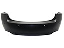 Chrysler Bumper Cover
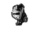 Chrysler Door Lock
 Chrysler Fender
 Chrysler Cigarette Lighter
 Chrysler Air Deflector
 Chrysler Car Mirror
 Chrysler Coil Spring Bracket
 Chrysler Exhaust Nut
 Chrysler Wheelhouse
 Chrysler Windshield Wiper
 Chrysler Wiper Arm
 Chrysler Wiper Motor