JeepParts
My Garage
My Account
Cart
OEM Dodge Durango Rod Bearing
Engine Connecting Rod Bearing- Select Vehicle by Model
- Select Vehicle by VIN
Select Vehicle by Model
orMake
Model
Year
Select Vehicle by VIN
For the most accurate results, select vehicle by your VIN (Vehicle Identification Number).
12 Rod Bearings found


Dodge Durango Connecting Rod Bearing Part Number: 5184111AF
$3.76 MSRP: $5.65You Save: $1.89 (34%)Ships in 1-2 Business Days


Dodge Durango Connecting Rod Bearing Part Number: 5184113AF
$3.83 MSRP: $5.65You Save: $1.82 (33%)Ships in 1-2 Business Days


Dodge Durango Connecting Rod Bearing Part Number: 4893952AA
$10.37 MSRP: $15.40You Save: $5.03 (33%)Ships in 1-3 Business Days


Dodge Durango Connecting Rod Bearing Part Number: 68362046AA
$16.59 MSRP: $24.55You Save: $7.96 (33%)Ships in 1-2 Business Days


Dodge Durango Bearings Part Number: 5012363AE
$16.87 MSRP: $25.00You Save: $8.13 (33%)Ships in 1-2 Business Days


Dodge Durango Bearings Part Number: 68052222AB
$18.13 MSRP: $26.80You Save: $8.67 (33%)Ships in 1-2 Business Days


Dodge Durango Connecting Rod Bearing Part Number: 68029429AC
$16.02 MSRP: $23.55You Save: $7.53 (32%)Ships in 1-2 Business Days


Dodge Durango Rod Bearings Part Number: 2421305
$21.97 MSRP: $27.86You Save: $5.89 (22%)Ships in 1-2 Business Days


Dodge Durango Connecting Rod Bearing Part Number: 68207790AA
$6.32 MSRP: $7.70You Save: $1.38 (18%)


Dodge Durango Connecting Rod Bearing Part Number: 4893953AA
$9.41 MSRP: $13.95You Save: $4.54 (33%)Ships in 1-2 Business Days


Dodge Durango Connecting Rod Bearing Part Number: 4893951AA
$14.57 MSRP: $15.05You Save: $0.48 (4%)Ships in 1-2 Business Days


Dodge Durango Connecting Rod Bearing Part Number: 5184112AF
$16.30 MSRP: $23.55You Save: $7.25 (31%)
Dodge Durango Rod Bearing
Choose OEM Rod Bearing that meet Dodge factory standards. Dodge designs and tests every component for precision and durability. Each Rod Bearing follows strict manufacturing steps to lock in quality and fit. If your Dodge Durango matters to you, OEM parts make the smart choice. You'll get the exact look, feel, and performance you expect. Shop genuine Durango parts at the highly competitive prices online. Enjoy a manufacturer's warranty, a hassle-free return policy, and rapid delivery. No more guesswork with off brands. Get genuine parts with exact fit and true factory performance. Shop with confidence today at JeepPartsDeal.com.
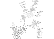
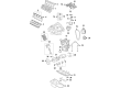
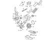
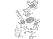
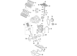
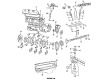
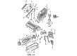
The Dodge durango Rod Bearing is a part that greatly improves the dependability of the series Dodge Durango. As an essential component of the crankshaft and camshaft, the Rod Bearing enables the safe rotation of the engines through the regular supply of viscosity oil by the pressure supplied by the engine's oil pump. Different kinds of Rod Bearings such as bi-metal and tri-metal types are installed in different Durango models respectively, and the materials of them are chosen on the aspects of strong intensity and fatigue performance. Another noteworthy bearing is the tri-metal Rod Bearing that commonly has a dry film lubricant that effectively cuts down on friction while increasing the bearing's strength for high power output engines. Such attention paid not only to the detail contributes to raising the efficiency of the Dodge Durango but also stands as one of the aspects that define the cars' safety for operation. That compatibility with the different Durango models from the V6 models to the powerful V8 engines shows that the rods are very flexible. Dodge Durango is truly a marked automaker in the auto industry even through its latest third generation, and the Rod Bearing is a classic example of this vehicle. Being another genius of the Dodge Durango, the Rod Bearing emphasizes the concentration on the vehicle's high performance, sturdiness, and reliability, which is of great importance for those people who prefer SUV automobiles.
Dodge Durango Rod Bearing Parts and Q&A
- Q: What Are the Key Considerations for Rod Bearing Installation and Lubrication on Dodge Durango?A:Keep all the rods together on one bank at a time, because connecting rods and Pistons cannot be swapped between banks. After you remove the bearing caps, mark them so they can be assembled correctly, because each is different from the others. Every bearing cap has a V-groove on the parting face; make sure the V-groove on the bottom shell matches the one on the cap to easily lubricate the opposite bank's cylinder wall. Put the bearing shells in the framework so that their tangs fit the machined grooves in the rods and caps. The taper or out-of-round on any crankshaft journal should never exceed 0.001 inch (0.025 mm). Bearings are sold in sizes that are 0.025 mm (0.001 inch), 0.051 mm (0.002 inch), 0.076 mm (0.003 inch), 0.254 mm (0.010 inch) and 0.305 mm (0.012 inch) less than standard. Be sure to put a pair of bearings in at a time, never use a new bearing half with an old one and don't file the bearing caps or rods.
- Q: How to Inspect and Replace Rod Bearings on Dodge Durango?A:Test the bearing surfaces for scoring and look for normal wear marks, grooves, fatigue and pitting. If a bearing looks abnormal, change it. Make sure you check the connecting rod journals for scoring, nicks and burrs, as incorrectly aligned or bent connecting rods can damage Pistons, piston rings, cylinder walls, connecting rod bearings and the journals of the crankshaft. Should the wearing of lubricant, bent parts or cracks point to the connecting rod not being aligned correctly, make sure it is and replace any misaligned, bent or twisted rods. Start by removing oil from the connecting rod journal, apply lube to the upper bearing insert and carefully place it in the connecting rod so it is centered. Test out two separate measurements, keeping the result below 0.50 mm (0.0196 in.). Mount Guide Pins Special Tool 8507 on a piston ring compressor to fit the rod and piston assembly into the engine, so the oil slinger slots are in front and the "F"'s on the pistons point that direction too. Put the lower bearing insert into the bearing cap, position it correctly and confirm it doesn't have any grease. Apply a band of Plastigage evenly around the entire central lower insert, without it crumbling; if it is crumbly, new stock should be purchased. Fix the bearing cap and connecting rod to the journal and fasten all bolts to 27 Nm (20 ft. lbs.) plus 90°, but don't rotate the crankshaft at this point to keep the Plastigage clean. After removing the bearing cap, measure the thickness of squashed Plastigage to find the clearance and compare it to the specification for this style of bearing. A change in clearance might mean the journal is tapered, the connecting rod is bent or there is foreign debris stuck between the insert and the cap or rod. Should the replacement part indicate the correct value, just pull the Plastigage from both items and continue with installation. If the bearing-to-journal gap is larger than specified, choose the type of bearing set required, since rod bolts are Torque to Yield and cannot be reused after removal. Measure with Plastigage once again before final assembly to check if the bearing is right. With the suitable insert found, place it and its cap, then screw the connecting rod bolts to a torque of 27 Nm plus a 90° turn. Gently insert the proper-size feeler gauge between the connecting rod and crank journal flange, as described in Engine Specifications and change the connecting rod if the side clearance is unsafe for the engine.


Related Dodge Durango Parts
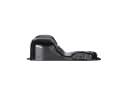 Dodge Durango Oil Pan
 Dodge Durango Oil Pump
 Dodge Durango Cam Gear
 Dodge Durango Cylinder Head
 Dodge Durango Motor And Transmission Mount
 Dodge Durango Oil Pan Gasket
 Dodge Durango Piston
 Dodge Durango Piston Ring Set
 Dodge Durango Pushrod
 Dodge Durango Rocker Arm
 Dodge Durango Valve Cover Gasket
 Dodge Durango Variable Timing Sprocket