JeepParts
My Garage
My Account
Cart
OEM Dodge Durango Timing Chain
Engine Timing Chain- Select Vehicle by Model
- Select Vehicle by VIN
Select Vehicle by Model
orMake
Model
Year
Select Vehicle by VIN
For the most accurate results, select vehicle by your VIN (Vehicle Identification Number).
7 Timing Chains found


Dodge Durango Timing Chain Part Number: 5184355AF
$34.43 MSRP: $50.85You Save: $16.42 (33%)Ships in 1-3 Business Days


Dodge Durango Timing Chain Part Number: 5184352AF
$147.90 MSRP: $259.00You Save: $111.10 (43%)Ships in 1-3 Business Days
Dodge Durango Timing Chain Part Number: 5047907AA
$41.74 MSRP: $84.60You Save: $42.86 (51%)Ships in 1-2 Business DaysDodge Durango Timing Chain Part Number: 5047963AB
$71.36 MSRP: $107.00You Save: $35.64 (34%)


Dodge Durango Timing Chain Part Number: 53022316AC
$65.71 MSRP: $96.70You Save: $30.99 (33%)


Dodge Durango Timing Chain Part Number: 83507095

Dodge Durango Timing Chain Part Number: 5019423AD
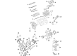
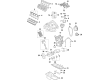
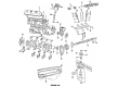
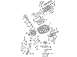
Dodge Durango Timing Chain
Choose OEM Timing Chain that meet Dodge factory standards. Dodge designs and tests every component for precision and durability. Each Timing Chain follows strict manufacturing steps to lock in quality and fit. If your Dodge Durango matters to you, OEM parts make the smart choice. You'll get the exact look, feel, and performance you expect. Shop genuine Durango parts at the highly competitive prices online. Enjoy a manufacturer's warranty, a hassle-free return policy, and rapid delivery. No more guesswork with off brands. Get genuine parts with exact fit and true factory performance. Shop with confidence today at JeepPartsDeal.com.
The Timing Chain in Dodge Durango is a critical component in the process of establishing the coordination in the functioning of the camshaft and crankshaft in order to bring about accurate valve timing which is paramount in determining the engine efficiency. Known as the Timing Chain, it operates at the front side of the engine and needs some kind of oil for it to work effectively, these are mostly seen in the large engines. Metal timing chains, also, have been deployed in Dodge Durango models, timing chains, generally, have become popular since the 1990s since they are durable and do not require frequent replacement in contrast to the rubber timing belts. Timing chains as a whole do not have many problems but sometimes, problems related to the lubrication or tensioner and chain guides appear, this is manifested by a rattling sound from the front of the engine.
Dodge Durango Timing Chain Parts and Q&A
- Q: How to Remove and Replace a Timing Chain and Sprockets on Dodge Durango?A:Before removing the chains and sprockets, disconnect the negative cable from the battery and drain coolant from the system. After that, loosen the cylinder head covers and then uninstall the radiator fan. Turn the engine slowly so that when the timing mark on the crankshaft damper lines up with the TDC mark on the timing chain cover, the "V6" at the top of the No. 1 camshaft sprocket also points at 12 o'clock. Lose the Power Steering Pump and disconnect the access plugs per cylinder head to get to the chain guide fasteners. Unbolt the oil fill housing to get at the right side tensioner arm fastener and after that remove the crankshaft damper and timing chain cover. Squeeze and clamp the primary chain tensioner; cover the oil pan to avoid anything dropping inside. After that, take out the two secondary chain tensioners and the Camshaft Position Sensor, taking care not to harm the camshaft target wheel. Do not turn the camshafts or crankshafts separately to stay safe. Take out the bolts on both camshaft sprockets, then fix the left camshaft steel tube in place with Camshaft Holder 8428A as you remove the left camshaft sprocket while turning the camshaft about 5 degrees clockwise. Repeat the whole process after you place the right camshaft sprocket on the crankshaft sprocket. Take out the idler sprocket assembly bolt and move the idler sprocket and crank sprocket assembly forward so the two chains will both come off. Also, take out the tensioner arms and the chain guides, then remove the primary chain tensioner at the end.
- Q: How to install a Timing Chain on Dodge Durango?A:Lift up the secondary chain tensioner piston lightly so it is even with the tensioner and while it is held, pull the ratchet pawl backward through the small opening on the tensioner body. After holding the pawl back, put the ratchet device about 2 mm from the tensioner, insert Special Tool 8514 lock pin into the front hole of the tensioner, then open the vise gently to deliver the piston spring pressure to the lock pin. Set the primary chain tensioner above the oil pump and push in bolts to the tensioner bracket's two lower holes while tightly fastening them to 28 Nm (250 in. lbs.). Install the right chain tensioner arm by turning the Torx bolt to 28 Nm (250 in. lbs.), then fasten the left side chain guide bolts to 28 Nm (250 in. lbs.). The next task is to install the left tensioner arm, fix it with a Torx bolt and make sure it is tightened to 28 Nm (250 in. lbs.). Then, install and tighten the chain guide on the opposite side to 28 Nm (250 in. lbs.). Attach the secondary chains to the idler sprocket, so the two metal links come out both hole openings, then hold the chains in place with Special Tool 8429. Attach the primary chain double plated links to the timing mark at 12 o'clock on the idler sprocket and align the single plated link with the timing mark at 6 o'clock on the crankshaft sprocket. Apply oil to the idler shaft and servo bushings, then fit all chains, the crankshaft sprocket and the idler sprocket together. Then, using the elastic strap, attach the both secondary chains to the block and cylinder head and install them. Deliver the timing mark on the idler sprocket gear to the one on the counterweight drive gear, set the sprocket into place, apply oil to the washer and tighten the bolt to a torque of 34 Nm (25 ft. lbs.). Before adding the sprockets, gently turn the Camshafts so the left camshaft's "L" dot aligns with the plated link on the chain and the right's "R" dot aligns with its respective link. Ensure there's not too much oil on the camshaft sprocket bolt when attaching the sliders and don't tighten the bolts yet. Place all plates so that their marks line up with the marks on the sprockets and put the "V6" mark on the camshaft sprockets at 12 o'clock, reminding you that the secondary chain tensioner plate should be on the left. Put in two secondary chain tensioners and screw the bolts on tight to 28 Nm (250 in. lbs.), remembering that left and right secondary chain tensioners are not always available. Harbors that handle these chains must remove all locktops, but they should not open the chain tensioner. Special Tool 6958 and Spanner with Adaptor Pins 8346 should be used to tighten the left camshaft sprocket bolts to 122 Nm (90 ft. lbs.) and the right camshaft sprocket bolts to 122 Nm (90 ft. lbs.). Turn the engine two full times and check that all the timing marks are correct: the primary chain idler sprocket dot is at 12 o'clock, the primary chain crankshaft sprocket dot is at 6 o'clock, the secondary chain camshaft sprockets say "V6" and are at 12 o'clock and the counterbalancer shaft drive gear dot is next to the idler sprocket gear dot. Put a drop of engine oil on each chain and set them all in place, then inspect the idler gear's end play which needs to be within 0.10 - 0.25 mm (0.004 - 0.010 in.); if it isn't, replace the idler gear. Place the timing chain cover and the crankshaft damper after that and once the cylinder head covers are in, seal the plug of the appropriate cylinder head with sealant to keep leaks from occurring. Cover the large threaded access plug with Mopar Thread Sealant with Teflon, fit it into the right cylinder head and tighten until you reach 81 Nm (60 ft. lbs.). Now, place the housing for the oil fill, attach the left cylinder head access plug, place the Power Steering Pump, fill the cooling system and tie the negative wire from the battery.


Related Dodge Durango Parts
 Dodge Durango Oil Filter
 Dodge Durango Oil Drain Plug
 Dodge Durango Oil Pan
 Dodge Durango Crankshaft
 Dodge Durango Cylinder Head Gasket
 Dodge Durango Dipstick Tube
 Dodge Durango Oil Filler Cap
 Dodge Durango Oil Pan Baffle
 Dodge Durango Piston Ring Set
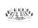 Dodge Durango Rocker Shaft Spring Kit
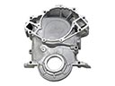 Dodge Durango Timing Cover
 Dodge Durango Valve Stem Seal