JeepParts
My Garage
My Account
Cart
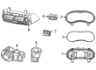
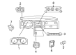
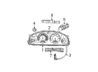
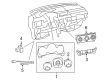
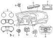
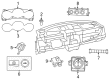
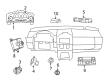
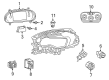
OEM Dodge Instrument Cluster
Speedometer Instrument Cluster- Select Vehicle by Model
- Select Vehicle by VIN
Select Vehicle by Model
orMake
Model
Year
Select Vehicle by VIN
For the most accurate results, select vehicle by your VIN (Vehicle Identification Number).
473 Instrument Clusters found


Dodge Cluster Lens Part Number: 68216990AA
$200.54 MSRP: $295.00You Save: $94.46 (33%)Ships in 1-3 Business DaysProduct Specifications- Other Name: Lens - Instrument Cluster; Instrument Panel Lens; Lens; Mask And Lens Instrument Cluster


Dodge Lens Part Number: 68057649AA
$436.25 MSRP: $637.00You Save: $200.75 (32%)Ships in 1-3 Business DaysProduct Specifications- Other Name: Mask - Instrument Cluster; Mask And Lens Instrument Cluster


Dodge Instrument Cluster Part Number: 4685952AB
$343.19 MSRP: $435.05You Save: $91.86 (22%)Ships in 1-2 Business DaysProduct Specifications- Other Name: Cluster - Instrument Panel; Cluster Instrument Panel

Dodge Cluster Lens Part Number: 68001782AA
$109.66 MSRP: $210.00You Save: $100.34 (48%)Ships in 1-2 Business DaysProduct Specifications- Other Name: Mask - Instrument Cluster; Instrument Panel Lens; Mask And Lens Instrument Cluster

Dodge Cluster Lens, Driver Side Part Number: 68092944AA
$109.01 MSRP: $193.00You Save: $83.99 (44%)Ships in 1-3 Business DaysProduct Specifications- Other Name: Lens - Instrument Cluster; Instrument Panel Lens, Left; Mask And Lens Instrument Cluster
- Position: Driver Side

Dodge Cluster Lens Part Number: 68092943AA
$109.01 MSRP: $193.00You Save: $83.99 (44%)Ships in 1-3 Business DaysProduct Specifications- Other Name: Lens - Instrument Cluster; Instrument Cluster Visor; Cluster Visor; Mask And Lens Instrument Cluster


Dodge Instrument Cluster Part Number: 68087325AD
$109.84 MSRP: $162.00You Save: $52.16 (33%)Ships in 1-3 Business DaysProduct Specifications- Other Name: Cluster - Instrument Panel
- Replaces: 68087325AC, 68087325AA, 68087325AB, 68036305AC

Dodge Cluster Lens Part Number: 68059179AA
$123.50 MSRP: $183.00You Save: $59.50 (33%)Ships in 1-3 Business DaysProduct Specifications- Other Name: Mask - Instrument Cluster; Instrument Panel Lens; Mask And Lens Instrument Cluster

Dodge Instrument Cluster Part Number: 68087330AD
$142.76 MSRP: $210.00You Save: $67.24 (33%)Ships in 1-3 Business DaysProduct Specifications- Other Name: Cluster - Instrument Panel
- Replaces: 68087330AB, 68087330AC, 68087330AA, 68036310AC

Dodge Instrument Cluster Part Number: 68036310AD
$160.89 MSRP: $237.00You Save: $76.11 (33%)Ships in 1-3 Business DaysProduct Specifications- Other Name: Cluster - Instrument Panel
- Replaces: 68036310AB, 68036310AA

Dodge Lens Part Number: 68089306AA
$196.01 MSRP: $291.00You Save: $94.99 (33%)Ships in 1-3 Business DaysProduct Specifications- Other Name: Mask - Instrument Cluster; Instrument Panel Lens; Mask And Lens Instrument Cluster; Mask Instrument Cluster

Dodge Instrument Cluster Part Number: 68036301AD
$214.14 MSRP: $315.00You Save: $100.86 (33%)Ships in 1-3 Business DaysProduct Specifications- Other Name: Cluster - Instrument Panel; Cluster Assembly
- Replaces: 68036301AA, 68036301AB

Dodge Cluster Assembly Part Number: 68242389AB
$219.80 MSRP: $324.00You Save: $104.20 (33%)Ships in 1-3 Business DaysProduct Specifications- Other Name: Cluster - Instrument Panel; Instrument Cluster
- Replaces: 56054667AD, 56054667AC, 68242389AA
Dodge Instrument Cluster Part Number: 68087322AD
$235.66 MSRP: $349.00You Save: $113.34 (33%)Ships in 1-3 Business DaysProduct Specifications- Other Name: Cluster - Instrument Panel; Cluster Assembly
- Replaces: 68087322AC, 68087322AA, 68036302AC, 68087322AB

Dodge Instrument Cluster Part Number: 68241687AA
$308.18 MSRP: $456.00You Save: $147.82 (33%)Ships in 1-3 Business DaysProduct Specifications- Other Name: Cluster - Instrument Panel; Cluster Assembly; Cluster Instrument Panel
- Replaces: 56054926AA


Dodge Instrument Cluster Part Number: 56045668AI
Product Specifications- Other Name: Cluster; Cluster Assembly
- Replaces: 56045668AG


Dodge Lens Part Number: 4829851AC
Product Specifications- Other Name: Mask - Instrument Cluster; Instrument Panel Lens; Mask And Lens Instrument Cluster For 6 Gauge; Mask And Lens Instrument Cluster


Dodge Instrument Cluster Part Number: 4685744AI
Product Specifications- Other Name: Cluster - Instrument Panel; Cluster Assembly; Cluster Instrument Panel
- Replaces: 4685744AE, 4685744AD


Dodge Instrument Cluster Part Number: 5174083AA
Product Specifications- Other Name: Cluster - Instrument Panel; Cluster; Cluster Instrument Panel
- Replaces: 5119415AA, 5166725AA

Dodge Cluster Lens Part Number: 68048516AA
Product Specifications- Other Name: Mask - Instrument Cluster; Mask And Lens Instrument Cluster
| Page 1 of 24 |Next >
1-20 of 473 Results
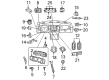
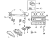
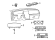
Dodge Instrument Cluster
OEM parts sourced directly from Dodge deliver superior quality, long lasting strength, and a precise fit you can trust. Each item goes through strict quality checks to ensure safety, toughness, and performance that matches your factory equipment. At JeepPartsDeal online shop, you'll get top-quality, budget-friendly OEM Dodge Instrument Cluster for your vehicle. We focus on giving you a high standard without pushing up the price. Our full selection of genuine factory products comes backed by the original manufacturer's warranty. You'll love our fast delivery, seamless shopping experience, and convenient return policy, saving you all the hassle.
Dodge Instrument Cluster has all the vital stats right in your eyes to ensure that decisions are prompt and secure. Dodge has been the symbol of unfiltered power, starting the first all-steel body, bringing forth HEMI thunder, firing Viper muscle, and with electric cars growling with the Fratzonic Chambered Exhaust, which switches between hush and drag-strip thunder at the command of a switch. Dodge does not make compromises, preferring aggressive lines, attitude, and variable drive modes that transform sleepy commuting to doses of adrenaline, although it supports the show with heavy construction that sends everyday dents and winter salt bouncing off, keeping the street credibility of the badge intact over decades to come. The grit of early machine-shop can still beat under all the hoods, as a reminder to the drivers that style is nothing when it comes to tough roads. Being directly above the wheel, the Instrument Cluster combines speed, rpm, fuel level, warning lights, and drive indicators into sharp analog dials and digital displays to enable motorists to view their performance, save gas, and respond to road conditions without having to look down or scroll through menus. Dodge Instrument Cluster also includes customizable lights, seat belts, and safety icon alerts where its owners can customize priorities that suit city errands or highway hauls without navigating the software labyrinths. The Instrument Cluster is easily fitted to a variety of dashboards throughout the range due to its modular dimensions, and therefore, it has earned its value across not just one car but also made upgrading in the future far easier.
Dodge Instrument Cluster Parts and Q&A
- Q: How to Remove the Instrument Cluster on Dodge Challenger?A:To remove the instrument panel on a Challenger model, first disconnect the cable from the negative terminal of the battery. Next, remove the center console, glove box, and steering column. Detach the A-pillar trim panels by prying the top away from the pillar, disconnecting the roof rail airbag electrical connector, and then removing the trim. Carefully pry up the defroster grille panel and detach it from the instrument panel. Unplug the electrical connectors at the bottom of each A-pillar, then remove the driver's knee bolster. Disconnect the electrical connectors under each end of the instrument panel, and remove the floor air duct along with the bolts from the instrument panel center brackets. Take out the two bolts from the forward edge of the instrument panel on the left side, followed by the screws from the center and right forward edge. Remove the instrument panel mounting bolts from each end, and with assistance, lift the instrument panel off the support hooks, ensuring nothing is still attached, and guide it out of the vehicle. Installation follows the reverse order of removal.
- Q: How to disconnect and remove the instrument cluster from the instrument panel on Dodge Neon?A:Disconnect and isolate the negative cable to prevent accidental contact with the battery negative terminal. Remove the instrument panel top cover and the instrument cluster bezel. Take out the four cluster mounting screws and separate the instrument cluster from the instrument panel. Disconnect any electrical connectors that may interfere with removal. Installation follows the reverse order of removal.


Related Dodge Parts
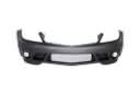 Dodge Bumper
 Dodge Door Lock
 Dodge Windshield
 Dodge Air Deflector
 Dodge Brake Master Cylinder Reservoir
 Dodge Door Hinge
 Dodge Door Latch Cable
 Dodge Door Lock Cylinder
 Dodge Rear Door Striker
 Dodge Shift Indicator
 Dodge Side View Mirrors
 Dodge Windshield Wiper