JeepParts
My Garage
My Account
Cart
OEM Chrysler Wheel Bearing
Hub Bearing- Select Vehicle by Model
- Select Vehicle by VIN
Select Vehicle by Model
orMake
Model
Year
Select Vehicle by VIN
For the most accurate results, select vehicle by your VIN (Vehicle Identification Number).
53 Wheel Bearings found


Chrysler Hub & Bearing, Rear Part Number: 4779869AC
$162.79 MSRP: $244.00You Save: $81.21 (34%)Ships in 1-2 Business DaysProduct Specifications- Other Name: Bearing - Wheel; Wheel Bearing and Hub Assembly; Hub Repair Kit; Axle Bearing.; Hub Assembly; Front & Rear Hub & Bearing Wheel Assembly; Wheel Bearing.
- Position: Rear
- Replaces: 4779869AA, 4779869AB


Chrysler Hub Assembly, Front Part Number: 4670292AC
$108.82 MSRP: $200.00You Save: $91.18 (46%)Ships in 1-2 Business DaysProduct Specifications- Other Name: Hub - Wheel; Wheel Hub, Front; Wheel Hub Repair Kit; Front Hub; Hub Wheel; Wheel Hub
- Position: Front


Chrysler Hub & Bearing, Rear Part Number: 68155868AB
$237.37 MSRP: $364.00You Save: $126.63 (35%)Ships in 1-2 Business DaysProduct Specifications- Other Name: Bearing - Wheel; Wheel Bearing and Hub Assembly, Rear; Wheel Hub Repair Kit; Wheel Hub Assembly; Wheel Hub; Hub & Bearing Assembly; Rear Hub & Bearing; Wheel Bearing and Hub Assembly
- Position: Rear


Chrysler Hub & Bearing, Rear Part Number: 4779328AB
$268.52 MSRP: $410.00You Save: $141.48 (35%)Ships in 1-2 Business DaysProduct Specifications- Other Name: Bearing - Brake; Wheel Bearing and Hub Assembly; Wheel Hub Repair Kit; Axle Bearing.; Hub Assembly; Front Hub & Bearing; Wheel Bearing and Hub Assembly.
- Position: Rear
- Replaces: 4779328AA, 4779218AB


Chrysler Hub & Bearing, Front Part Number: 68302651AA
$371.28 MSRP: $565.00You Save: $193.72 (35%)Product Specifications- Other Name: Bearing - Brake; Front Wheel Bearing and Hub Assembly; Wheel Hub Repair Kit; Axle Bearing.; Hub Assembly; Front Hub & Bearing; Hub And Bearing Brake; Wheel Bearing and Hub Assembly; Wheel Bearing
- Position: Front
- Replaces: 5154262AA, 5154262AB


Chrysler Wheel Bearing, Rear Part Number: 3507898AB
$58.43 MSRP: $87.55You Save: $29.12 (34%)Ships in 1-2 Business DaysProduct Specifications- Other Name: Bearing - Axle Shaft; Drive Axle Shaft Bearing, Rear; Differential Bearing; Axle Bearing; Axle Bearings; Bearing Assembly; Differential Cover Bearing; Bearing; Bearing Axle Shaft; Bearing Wheel
- Position: Rear

Chrysler Hub Assembly, Front Part Number: 4670292AF
$94.61 MSRP: $143.00You Save: $48.39 (34%)Ships in 1-2 Business DaysProduct Specifications- Other Name: Hub - Wheel; Wheel Hub, Front; Wheel Hub Repair Kit; Front Hub; Hub Wheel; Wheel Hub
- Position: Front
- Replaces: 4670292AE


Chrysler Hub Assembly, Front Part Number: 68346842AA
$160.56 MSRP: $240.00You Save: $79.44 (34%)Ships in 1-2 Business DaysProduct Specifications- Other Name: Hub - Wheel; Front Wheel Bearing and Hub Assembly; Wheel Hub Repair Kit; Axle Bearing.; Front Hub & Bearing
- Position: Front
- Replaces: 68137552AB, 68137552AC, 68137552AA


Chrysler Hub & Bearing, Front Part Number: 4779199AA
$182.86 MSRP: $274.00You Save: $91.14 (34%)Ships in 1-2 Business DaysProduct Specifications- Other Name: Bearing - Brake; Front Wheel Bearing and Hub Assembly; Wheel Hub Repair Kit; Axle Bearing.; Hub Assembly; Front Hub & Bearing; Hub And Bearing Brake; Wheel Bearing and Hub Assembly; Wheel Bearing
- Position: Front


Chrysler Hub Assembly, Front Part Number: 5154211AA
$217.43 MSRP: $325.00You Save: $107.57 (34%)Ships in 1-2 Business DaysProduct Specifications- Other Name: Hub & Bearing - Wheel; Front Wheel Bearing and Hub Assembly; Repair Kit; Bearing Kit; Axle Bearing.; Front Hub & Bearing; Hub And Bearing Wheel; Wheel Bearing and Hub Assembly; Wheel Bearing
- Position: Front
- Replaces: 5085406AB, 5085406AC, 5105233AB, 5105233AC


Chrysler Hub & Bearing, Rear Part Number: 68184746AE
$54.87 MSRP: $78.85You Save: $23.98 (31%)Product Specifications- Other Name: Bearing - Brake; Rear Wheel Bearing and Hub Assembly; Hub Repair Kit.; Hub & Bearing Assembly; Rear Hub & Bearing; Wheel Bearing and Hub Assembly
- Position: Rear
- Replaces: 68184746AC, 68184746AD, 68184746AA, 5154198AB, 5154198AD, 5154198AC, 68184746AB


Chrysler Hub & Bearing, Front Part Number: 4578144AB
$248.54 MSRP: $318.00You Save: $69.46 (22%)Ships in 1-2 Business DaysProduct Specifications- Other Name: Bearing - Brake; Front Wheel Bearing and Hub Assembly; Wheel Hub Repair Kit; Axle Bearing.; Hub Assembly; Front Hub & Bearing; Front Hub; Hub And Bearing Brake; Wheel Bearing and Hub Assembly; Wheel Bearing
- Position: Front
- Replaces: 4593462AA, 4578144AA
Chrysler Hub & Bearing Part Number: 4616263AA
$19.82 MSRP: $114.00You Save: $94.18 (83%)Ships in 1-2 Business DaysProduct Specifications- Other Name: Hub - Brake; Wheel Bearing and Hub Assembly; Wheel Hub Repair Kit; Wheel Hub Module; Wheel Hub Assembly.; Hub

Chrysler Hub & Bearing, Rear Driver Side Part Number: 4766771AD
$75.99 MSRP: $337.00You Save: $261.01 (78%)Ships in 1-2 Business DaysProduct Specifications- Other Name: Hub & Bearing - Brake; Rear Left Wheel Bearing and Hub Assembly; Wheel Hub Repair Kit.; Hub Assembly; Hub & Bearing Assembly
- Position: Rear Driver Side
- Replaces: 5105771AA, 5105771AB, 4766771AA, MN101475

Chrysler Hub & Bearing, Rear Part Number: 68429526AA
$219.95 MSRP: $467.00You Save: $247.05 (53%)Ships in 1-2 Business DaysProduct Specifications- Other Name: Bearing - Brake; Wheel Bearing and Hub Assembly, Rear; Wheel Hub Repair Kit; Wheel Hub; Hub And Bearing Brake; Wheel Bearing
- Position: Rear
- Replaced by: 68429526AB
- Replaces: 68223512AC, 68223512AD, 68223512AE, 68223512AB

Chrysler Hub & Bearing Part Number: 4721515
$152.71 MSRP: $279.00You Save: $126.29 (46%)Ships in 1-2 Business DaysProduct Specifications- Other Name: Bearing - Brake; Wheel Bearing and Hub Assembly; Hub Repair Kit.; Hub; Hub And Bearing And Seal Assembly (W/Tone Ring); Hub And Bearing Brake

Chrysler Hub & Bearing, Front Part Number: 4641517AD
$323.46 MSRP: $538.00You Save: $214.54 (40%)Ships in 1-2 Business DaysProduct Specifications- Other Name: Bearing - Brake; Front Wheel Bearing and Hub Assembly; Wheel Hub Repair Kit; Axle Bearing.; Front Hub & Bearing; Front Hub; Hub And Bearing Brake; Wheel Bearing and Hub Assembly; Wheel Bearing; Hub Assembly
- Position: Front

Chrysler Hub & Bearing Part Number: 68522905AB
$163.91 MSRP: $250.00You Save: $86.09 (35%)Product Specifications- Other Name: Hub - Brake
- Replaced by: 68522905AC
- Replaces: 68328069AA, 68522905AA


Chrysler Hub & Bearing, Rear Part Number: 5181925AC
$181.28 MSRP: $267.00You Save: $85.72 (33%)Product Specifications- Other Name: Hub - Brake; Wheel Bearing and Hub Assembly, Rear; Wheel Bear & Hub Assembly; Wheel Hub Repair Kit; Wheel Hub; Hub Assembly; Rear Hub & Bearing; Wheel Bearing and Hub Assembly.
- Position: Rear
- Replaces: 5181925AB


Chrysler Front Wheel Bearing Part Number: 5272448AA
Product Specifications- Other Name: Bearing - Wheel; Wheel Bearing, Front; Wheel Bearing Kit; Axle Bearing; Bearing; Bearing Wheel; Wheel Bearing
- Position: Front
| Page 1 of 3 |Next >
1-20 of 53 Results
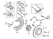
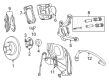
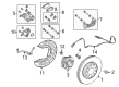
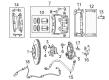
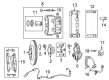
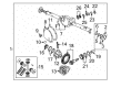
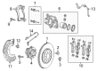
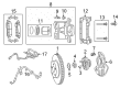
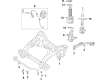
Chrysler Wheel Bearing
OEM parts sourced directly from Chrysler deliver superior quality, long lasting strength, and a precise fit you can trust. Each item goes through strict quality checks to ensure safety, toughness, and performance that matches your factory equipment. At JeepPartsDeal online shop, you'll get top-quality, budget-friendly OEM Chrysler Wheel Bearing for your vehicle. We focus on giving you a high standard without pushing up the price. Our full selection of genuine factory products comes backed by the original manufacturer's warranty. You'll love our fast delivery, seamless shopping experience, and convenient return policy, saving you all the hassle.
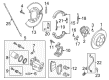
Chrysler Wheel Bearing ensures that the wheels revolve without distracting drag and enhances daily driving self-assurance. Chrysler earned its reputation by taking good bodies and combining them with such visions as Floating Power that smoothed the shake of engines, bold Airflow styling that cut the wind, and the first minivan that enabled families to jump in easily, all sold without nonsense games on prices so people could believe the cars were part of their lives. Buyers could enjoy reliable starters, strong brakes, and gauges that told the truth when making long hauls on the highway. Chrysler continues to maximize cabin space, ride comfort, and utility, and car owners and drivers have the advantage of spacious seats, predictable handling, easy-to-use gauges, deep pockets, and roomy materials, which simply shrug off abuse, good visibility, and quiet driving behavior, which made the commute relaxing. Each hub has in place Wheel Bearing, made of steel races over which roll polished balls to slice friction, dissipate heat, and keep tires running straight as the odometer clocks off miles. When a Wheel Bearing on the Chrysler is beginning to wear off, you hear growls and also feel the vibration before it fails. You might easily tell that it is time to replace the sealed unit rather than wait and see it wobble, tear tires, and overstretch the suspension. Fresh grease, regular inspection, and spec torque prevent every Wheel Bearing from locking up so that the ABS sensor will scan clean and the wheel turns in line with the braking and steering. Install an premium-grade Chrysler Wheel Bearing, screw it onto your car, and you regain easy movement, reliable brakes, and confidence without a squeak over every mile.
Chrysler Wheel Bearing Parts and Q&A
- Q: How to Service and Repair a Wheel Bearing on an AWD on Chrysler Town & Country?A:Before starting the repair or servicing of the wheel bearing, set the parking brake to prevent the hub, bearing and axle shaft from turning when you loosen the hub nut. Lift the vehicle up and take off the wheel/tire combination. After that, remove the cotter pin and nut retainer from the stub shaft of the outer C/V joint, along with the spring washer, hub nut and washer. Correctly remove six bolts that secure the driveshaft inner joint to the output shaft of the rear drive line module and then take off the rear wheel speed sensor from the rear hub/bearing. Unlock the parking brake and free the disc brake caliper by removing the bolts above the adapter, lifting the caliper front up and pulling it and its anti-rattle clip out from the bottom of the adapter. Make sure to support the caliper while removing the rotor from the hub/bearing, so you don't damage the hose. Crank down the inner joint and remove it from the drive line module. After that, pull the outer joint out from the hub/bearing. Do not tighten so much that it could damage the hub/bearing because of corrosion. If it's necessary, gently tap the disc brake caliper adapter with a soft-faced hammer to get the hub/bearing released. When the hub/bearing is immovable after being removed, use Remover, Special Tool 8214-1 to separate it from the caliper adapter. Put the hub/bearing onto the axle, attach it with the mounting bolts and tighten the bolts in a crisscross pattern to 129 Nm. Slide the covers of the driveshaft onto the hub/bearing and the output shaft and press them together to secure them both. After that, secure the rotor and set the brake caliper and shoes into place on the caliper adapter so that the guide pin bolts are not mixed up and the bolts are tightened to 35 Nm (26 ft. lbs.). First, wipe down the outer C/V joint ending, next install the washer and nut and then settle the vehicle to the ground. Once more, fix the parking brake so that driveshaft rotation doesn't take place when you tighten the driveshaft inner joint to the driveshaft side of the drive line module shaft bolts to 61 Nm (45 ft. lbs.) and then tighten the C/V joint hub nut to the C/V joint side of the driveshaft to 244 Nm (180 ft. lbs.). Attach the spring washer, nut retainer and cotter pin to the stub shaft, then put the wheel speed sensor in place with its attaching bolt and tighten it to 12 Nm (105 in. lbs.). Mount and secure the wheel and tire, tightening the six wheel mounting stud nuts sequentially half way, then restarting at the first stud nut for a full torque of 135 Nm (100 ft. lbs.). With the car on the ground, push the brake pedal a few times before you test the vehicle on the road to see that the brakes are working properly.
- Q: How to Properly Install a Wheel Bearing on Chrysler Crossfire?A:Before fitting the wheel bearing, apply grease to the front wheel hub, grease the lip of the radial ring and put grease between the wheel hub and the bearing. After that, fit the front wheel hub 1, the little one and the inner tapered bearing 2 onto the spindle. Secure the rotor with the hub nut 3 and after that, install the disc brake rotor 1 and the disc brake caliper 6. Check the level of wheel bearing end play and connect the dust cover in place. Just before driving, press down on the brake pedal a few times to get the system ready. In the end, install the tire and wheel combination.


Related Chrysler Parts
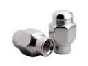 Chrysler Lug Nuts
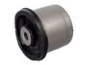 Chrysler Axle Beam Mount
 Chrysler Axle Pivot Bushing
 Chrysler Axle Shaft Seal
 Chrysler Control Arm Bolt
 Chrysler Control Arm Shaft Kit
 Chrysler Crossmember Bushing
 Chrysler Differential Mount
 Chrysler Leaf Spring
 Chrysler Spindle
 Chrysler Sway Bar Bracket
 Chrysler Sway Bar Link Bushing