JeepParts
My Garage
My Account
Cart
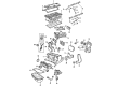
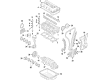
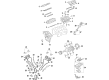
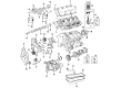
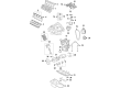
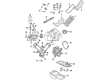
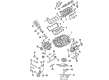
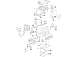
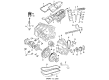
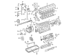
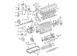
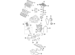
OEM Dodge Rod Bearing
Engine Connecting Rod Bearing- Select Vehicle by Model
- Select Vehicle by VIN
Select Vehicle by Model
orMake
Model
Year
Select Vehicle by VIN
For the most accurate results, select vehicle by your VIN (Vehicle Identification Number).
54 Rod Bearings found


Dodge Bearings Part Number: 5174612AA
$14.57 MSRP: $24.10You Save: $9.53 (40%)Product Specifications- Other Name: Bearing - Connecting Rod; Bearing Kit Connecting Rod Standard See Note; Bearing Kit Connecting Rod Standard
- Replaces: 5093448AB, 5012588AA


Dodge Bearings Part Number: 4884913AB
$2.34 MSRP: $3.55You Save: $1.21 (35%)Ships in 1-2 Business DaysProduct Specifications- Other Name: Bearing - Connecting Rod; Rod Bearing; Bearing Connecting Rod +3 Micron See Note
- Replaces: 1115A151, 4884913AA


Dodge Connecting Rod Bearing Part Number: 5184111AF
$3.76 MSRP: $5.65You Save: $1.89 (34%)Ships in 1-2 Business DaysProduct Specifications- Other Name: Bearing - Connecting Rod; Rod Bearing; Bearing; Bearings; Bearing Connecting Rod +.003Mm See Note; Bearing Connecting Rod +.003Mm
- Replaces: 5184111AE


Dodge Bearings Part Number: 4884911AB
$4.79 MSRP: $7.20You Save: $2.41 (34%)Ships in 1-2 Business DaysProduct Specifications- Other Name: Bearing - Connecting Rod; Rod Bearing; Bearing Connecting Rod-3 Micron See Note
- Replaces: 4884911AA, 1115A149


Dodge Connecting Rod Bearing Part Number: 5184113AF
$3.83 MSRP: $5.65You Save: $1.82 (33%)Ships in 1-2 Business DaysProduct Specifications- Other Name: Bearing - Connecting Rod; Rod Bearing; Bearing; Bearings; Bearing Connecting Rod - .003Mm See Note; Bearing Connecting Rod - .003Mm
- Replaces: 5184113AE


Dodge Connecting Rod Bearing Part Number: 4893952AA
$10.37 MSRP: $15.40You Save: $5.03 (33%)Ships in 1-3 Business DaysProduct Specifications- Other Name: Bearing - Connecting Rod; Rod Bearing; Bearings; Bearing Connecting Rod Standard
- Replaces: 4893836AA, 68088069AA


Dodge Connecting Rod Bearing Part Number: 4626657AD
$16.53 MSRP: $24.35You Save: $7.82 (33%)Ships in 1-2 Business DaysProduct Specifications- Other Name: Bearing Package - Connecting Rod; Bearings; Bearing Package Connecting Rod Standard
- Replaces: 4626657AB, 4626657AC


Dodge Connecting Rod Bearing Part Number: 68362046AA
$16.59 MSRP: $24.55You Save: $7.96 (33%)Ships in 1-2 Business DaysProduct Specifications- Other Name: Bearing Package - Connecting Rod; Rod Bearing; Bearing; Bearings; Bearing Kit Connecting Rod Standard Upper And Lower; Bearing Kit Connecting Rod Standard
- Replaces: 5086003AD, 5086003AC, 5086003AE


Dodge Bearings Part Number: 5012363AE
$16.87 MSRP: $25.00You Save: $8.13 (33%)Ships in 1-2 Business DaysProduct Specifications- Other Name: Bearing - Connecting Rod; Rod Bearing; Bearing Kit Connecting Rod Standard See Note; Bearing Kit Connecting Rod Standard
- Replaces: 5012363AC, 5012363AD, 5018584AB, 5012363AB


Dodge Bearings Part Number: 68052222AB
$18.13 MSRP: $26.80You Save: $8.67 (33%)Ships in 1-2 Business DaysProduct Specifications- Other Name: Bearing - Connecting Rod; Engine Connecting Rod Bearing Set; Connecting Rod Bearing Set; Rod Bearing; Bearing Kit Connecting Rod Standard See Note
- Replaces: 5019447AA, 68052222AA


Dodge Connecting Rod Bearing Part Number: 68002286AC
$18.22 MSRP: $27.05You Save: $8.83 (33%)Ships in 1-3 Business DaysProduct Specifications- Other Name: Bearing Kit - Connecting Rod; Engine Connecting Rod Bearing Set; Connecting Rod Bearing Set; Rod Bearing; Bearings; Bearing Kit Connecting Rod Standard
- Replaces: 68002286AA, 68002286AB


Dodge Bearings Part Number: 5161294AA
$18.30 MSRP: $27.05You Save: $8.75 (33%)Ships in 1-2 Business DaysProduct Specifications- Other Name: Bearing Kit - Connecting Rod; Bearing Package Connecting Rod Standard: One [1] Upper & One [1] Lower Bearing.
- Replaces: 5012056AA


Dodge Bearing Part Number: 5102123AA
$33.86 MSRP: $49.90You Save: $16.04 (33%)Ships in 1-3 Business DaysProduct Specifications- Other Name: Bearing - Connecting Rod; Rod Bearing; Bearings; Bearing Connecting Rod Standard


Dodge Bearing Part Number: 68001948AA
$38.31 MSRP: $57.00You Save: $18.69 (33%)Ships in 1-2 Business DaysProduct Specifications- Other Name: Bearing - Connecting Rod; Rod Bearing; Bearings; Bearing Connecting Rod Standard
- Replaces: 4429175, 4429175AB


Dodge Connecting Rod Bearing Part Number: 68029429AC
$16.02 MSRP: $23.55You Save: $7.53 (32%)Ships in 1-2 Business DaysProduct Specifications- Other Name: Bearing - Connecting Rod; Rod Bearing; Bearing; Bearings; Bearing Kit Connecting Rod Standard
- Replaces: 68029429AB, 68029429AA, 68029429AI, 68060359AA


Dodge Bearings Part Number: 4884912AB
$18.19 MSRP: $23.55You Save: $5.36 (23%)Product Specifications- Other Name: Bearing - Connecting Rod; Rod Bearing; Bearing Connecting Rod Standard See Note
- Replaces: 1115A150, 4884912AA


Dodge Rod Bearings Part Number: 2421305
$21.97 MSRP: $27.86You Save: $5.89 (22%)Ships in 1-2 Business DaysProduct Specifications- Other Name: Bearing Package - Connecting Rod; Engine Connecting Rod Bearing; Connecting Rod Bearing Pair; Rod Bearing; Bearings; Connecting Rod Bearing Package, Standard; Includes various connecting rod bearings.


Dodge Connecting Rod Bearing Part Number: 68207790AA
$6.32 MSRP: $7.70You Save: $1.38 (18%)Product Specifications- Other Name: Bearing Package - Connecting Rod; Rod Bearing; Bearing; Bearings; Bearing Kit Connecting Rod Standard
- Replaces: 5086003AB

Dodge Connecting Rod Bearing Part Number: 5047638AC
$3.99 MSRP: $6.00You Save: $2.01 (34%)Ships in 1-2 Business DaysProduct Specifications- Other Name: Bearing - Connecting Rod; Rod Bearing; Bearing; Bearings; Bearing Connecting Rod +3 Micron Used For Upper And Lower; Bearing Connecting Rod +3 Micron See Note
- Replaces: 5047638AB


Dodge Connecting Rod Bearing Part Number: 4893953AA
$9.41 MSRP: $13.95You Save: $4.54 (33%)Ships in 1-2 Business DaysProduct Specifications- Other Name: Bearing - Connecting Rod; Rod Bearing; Bearings; Bearing Connecting Rod - .003Mm; Bearing Connecting Rod - .006Mm
- Replaces: 4893837AA, 68088070AA
| Page 1 of 3 |Next >
1-20 of 54 Results
Dodge Rod Bearing
OEM parts sourced directly from Dodge deliver superior quality, long lasting strength, and a precise fit you can trust. Each item goes through strict quality checks to ensure safety, toughness, and performance that matches your factory equipment. At JeepPartsDeal online shop, you'll get top-quality, budget-friendly OEM Dodge Rod Bearing for your vehicle. We focus on giving you a high standard without pushing up the price. Our full selection of genuine factory products comes backed by the original manufacturer's warranty. You'll love our fast delivery, seamless shopping experience, and convenient return policy, saving you all the hassle.
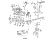
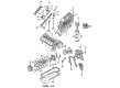
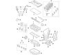
Dodge Rod Bearing is applied to maintain the crank rotation without any complications, cutting friction and protecting engine power. Dodge was no jester when it came to muscle matters, and since 1914, the company introduced all-steel bodies that laughed at potholes. In the future, Dodge crammed HEMI powerplants and Viper DNA in street cars, and high horsepower became commonplace. The Fratzonic Chambered Exhaust allows Dodge to shout when the batteries are swapped with the fuel, but a stealth mode will keep its neighbors at ease. Since out of drag-strip drive modes, donut-ready chassis tunes, the company has maintained fun at the heart of each launch. With one button press, drivers can switch between Sport or Stealth depending on the mood and hear thunder or hush wind, and do not need translation. That noise and control combination between tradition and modern is the way tradition is changing without giving up the rush. A Rod Bearing lies between the crankshaft and connecting rod, creating a smooth film of oil transforming metal grind into smooth glide. This Rod Bearing supports explosive loads of combustion and does not scar journals in any Dodge engine. Trimetal Rod Bearing solutions include a copper shield that shocks off anything vicious and elevated revs. Surface bare coated Rod Bearing surfaces are further trimmed to offer better startup wear and extended service miles. That stability allows cams to pursue greater lift and time without increasing the vibration civil or the horsepower ascending.
Dodge Rod Bearing Parts and Q&A
- Q: How to Properly Install Rod Bearings and Ensure Optimal Performance on Dodge Challenger?A:The caps need to be labeled before removing, as they cannot be switched and you should use a wood stand rather than a metal one. The bearing shells go on with the tangs in the proper grooves of the rods and caps, making certain the cap's tang points to the same side as the rod. Every non-assembled rod on the bank should be fitted with limits for out-of-round held to 0.008 mm (0.0003 in.) applied to its crankshaft journal. They are standard, 0.025 mm (0.001 in.) and 0.254 mm (0.010 in.) undersized and should always be installed as a pair, either new or worn. Plastigage should be used to measure both the main bearing and connecting rod bearing clearance and any necking on the rod bearing bolts should be checked; damaged bolts have to be replaced. A straight edge or scale should be used to check the bolts for stretching: if all threads don't contact the scale, replace the bolts. Before you fit them, remove any dirt from the threads, carefully look them over and install clean bolts with your fingers. Then, turn each one (while tightening them alternately) to the recommended assembly torque. To measure connecting rod side clearance, install a dial indicator at a stationary place on the engine block, making sure the probe is against the connecting rod cap you are examining. Tilt the connecting rod toward the backmost position, zero the dial, move it forward as far as you can, read the length and compare it to what is specified. Please follow the same steps for all the connecting rods as you turn the crankshaft to allow for a proper view.
- Q: What Precautions Should Be Taken When Fitting Rod Bearings During Assembly on Dodge Charger?A:Work on each connecting rod set, joining them one by one and paying attention to the unmarked bearing caps, marking each when it's taken off for correct assembly later. Don't use a punch to mark the rods and make sure you don't scratch the surfaces on where the fractured rod and cap meet, because this can damage the engine. Put the bearing shells on the rods so that the tangs slide into the machined holes and check that the hole in the upper bearing is on the same side as the squirt hole in the rod. The maximum taper allowable on a crankshaft journal is 0.015 mm (0.0006 in.), while the out-of-round tolerance is 0.010 mm (0.0004 in.). The bearings are supplied smaller than required by 0.001 inch or 0.0025 inch and this is added during installation. It is necessary to install two bearings of the same age in each location and never mix old with new or file the rods and bearing caps. For main bearing and connecting rod bearing clearance, put some plastigage in place and find the clearance standards in the engine handbook. If the threads of your connecting rod bearing cap bolts look stretched, replace the bolts. Rod cap bolts are held simply by a mild press and to remove them, carefully hammer out the bolt head with a punch to avoid damaging the rod cap. Press a scale against the threads; if some places on the threads are empty, change the bolt immediately. First, grease the threads with oil, put bolts in by hand and sync the bolts by alternately tightening them to specification. First, use a dial indicator on a fixed part of the engine and locate the dial on the cap of the connecting rod. Set the dial to zero, lower the connecting rod fully, read the indicator and compare the result to the listed specs, repeating this for every rod and as you rotate the crankshaft for access.


Related Dodge Parts
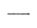 Dodge Camshaft
 Dodge Engine Cover
 Dodge Harmonic Balancer
 Dodge Timing Chain
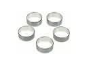 Dodge Camshaft Bearing
 Dodge Camshaft Plug
 Dodge Crankshaft Pulley
 Dodge Exhaust Valve
 Dodge Oil Pan Baffle
 Dodge Oil Pump Rotor Set
 Dodge Timing Cover Gasket
 Dodge Valve Guide
Browse Dodge Rod Bearing by Models
Charger Challenger Ram 1500 Dakota Durango Viper Dart Grand Caravan Ram 2500 Journey Caravan Avenger D100 D150 Magnum Neon Nitro Raider Stealth Caliber Ramcharger Dynasty Intrepid Ram 3500 Shadow Spirit Stratus Ram 50 W250 600 B250 B350 Colt D250 D350 Daytona Diplomat Hornet Sprinter 2500 Sprinter 3500 W100 W150 W350 Lancer B150 Mini Ram